
The common-or-garden vacuum cleaner is one of the most interesting gadgets in any house, because you can do so many things with it – almost none of which the makers of the vacuum cleaner intended !
Here we look at things at firing projectiles, running steam engines, pumping water, and all manner of other things, all using your vacuum cleaner. And we reveal how one projectile launch went further on Planet Earth than it would have done on the Moon or Mars !
- Vacuum Bazookas – you can suck things into a vacuum cleaner at high speed – but can you get them out again ? #vacuum bazookas
- Vacuum Engines – steam engines just like the ones which launched the Industrial Revolution #vacuum engines
- Vacuum Railroad – build your own ‘Hyperloop’ #vacuum railroads
- Vacuum Wall Climbing – stick to a wall like a gecko #vacuum wall climbing
…
…
Vacuum Bazookas
Wage War on Dirt -and fire projectiles – with your Vacuum Cleaner ! The Vacuum Bazooka uses the power of your vacuum to launch projectiles. The simplest version appeared in my book Vacuum Bazookas, Electric Rainbow Jelly, but since then I’ve made a few different ones, and people – you guys ! – have made bazillions of different versions. There have been Vacuum Bazookas that fire multiple shots, multiple shots from one barrel, Vacuum Bazookas that fire a ‘whole nine yards’ of shots from belted cartridges. And by moving to a source of more serious vacuum than a cleaner – a laboratory high vacuum pump – ping pong balls and even more unlikely projectiles have been shot through beer cans and even more unlikely targets !
Rather than using pressurized air or gas, the Vacuum Bazooka generates a vacuum in front of a projectile and uses the pressure of the atmosphere behind it to propel the projectile. This is surprisingly effective. In a competition, kids with various ordinary vacuum cleaners managed to get projectiles without streamlining or fins to whizz along an arc into the air, landing from 90 to 110m from launch point. Finned projectiles go much further – almost two football pitched on one occasion. One pair managed to do even better by an almost unbelievable fluke: they dutifully measured out the 200m or so that their projectile went in front of the group. Then there was much laughter: they owned up that the cylinder of light pine they had launched had been caught in mid-air by a bird – a large herring gull. The gull carried it for a while and then released it further down the playing fields, giving them the event record distance ! We later discussed projectiles and how they would go in the reduced gravity and very low pressure atmosphere of the Moon and Mars. However, the winning team pointed out that only on Earth could a projectile go for hundreds of meters with the same launch speed, as there are no seagulls on the Moon or Mars !
The use of vacuum technology for powering things preceded the system we use today for powering most things – electricity – by over two hundred years. The Boulton and Watt factory had a large vacuum pipe they named the ‘spirit pipe’ down the middle. A large steam engine pump produced the partial vacuum in it which was used to power all sorts of machines from coining presses to drills. Vacuum is still used today in some places. For example, in most cars vacuum is used for the vital function of braking, as well as in minor functions like the vacuum-powered valves for air conditioning. Servo brakes use vacuum to add force to that exerted by the driver on the brake pedal. The vacuum power comes from the low pressure generated in the air intake of petrol (gasoline) and diesel engines.
Had electricity been slower in coming, and had a suitable rubber or plastic seal been available, it is quite possible that today’s subway trains would still be using this system. The cleanliness of the vacuum system would be a particular advantage underground, and the system has safety advantages that could still be useful today. And we might be plugging in all our domestic appliances, from food mixers to portable drills, into the vacuum, not into the electrical mains !

Here is a short video showing the essentials on a simple vacuum bazooka, a video done for the guys at Physics World magazine. Enjoy!https://www.youtube.com/watch?v=7cFW5Zqcbgo&t=14s
And one from the Michael de Podesta (from the National Physical Laboratory) and his family. It includes some slow-motion video so that you can see the projectile emerging at high speed from behind the muzzle paper / flap https://www.youtube.com/watch?v=UgqaK9j1NLw
What You Need
- Piece of plastic drainpipe and a T-piece, eg. from 15mm to 35 mm bore
- Vacuum cleaner
- Soft wood, cork (champagne corks work !) or balsa wood projectile that fits inside the drainpipe snugly but slides freely
- Piece of heavy gauge paper, thin card or thin plastic
- Piece of hard sponge rubber or plastic (perhaps half a sponge ball) to put soft nose on hard projectiles
- Duck tape
- Light flaps with hinges, instead of heavy paper (optional)
What You Do
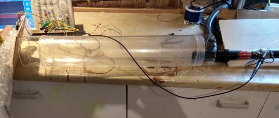
Assemble the cross-arm of the T-piece onto the end of the drainpipe as shown in the diagram, making sure that the T-piece presents no obstacles to the free passage of the projectile. The T-piece may have small tabs molded into its inner surface to locate fitted pipes precisely. If these stick out into the bore, they must be removed. If using an O-ring sealed tee, put a smear of ‘vaseline’ or similar clear grease on the tee where the pipes go in. If using a tee that would in use as drain pipes be glued, just push the pipes in and tape them. Then connect the vacuum cleaner hose to the T-piece, using tape to give a reasonable seal. Switch on the vacuum cleaner to suck the air out of the drainpipe.
Safety: the projectiles can be made of cork and weighted, which is convenient, and the lowish mass and soft nature of the projectiles makes them reasonably safe if they hit a person. However, there is a potential serious problem with eye impact, so always ensure that no one is in the way of the projectile’s trajectory. Outside you can lay out a ‘firing range’ to ensure this. Indoors, you should arrange for projectiles to hit something that will absorb their energy : a dangling heavy piece of cloth, perhaps. You could also enclose the trajectory in a long piece of (clear) strong plastic pipe.
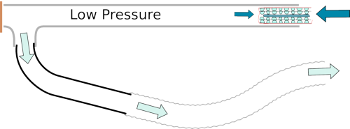
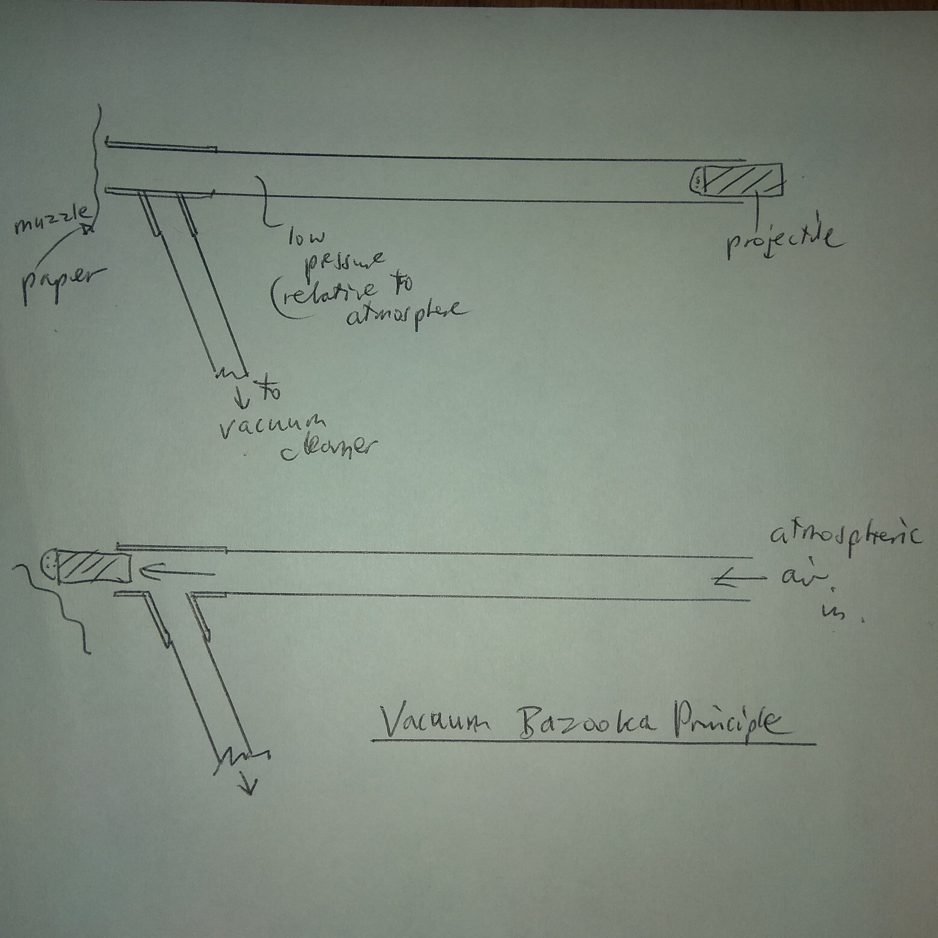
Now partially insert the projectile at the end of the pipe, making sure that you keep a good grip on it. Then take aim with the end of the T-piece (the muzzle), and put a piece of paper over the muzzle. You will now feel the atmosphere pushing hard and you will find it difficult to keep hold of the projectile, indicating a good vacuum. You will hear the note of the vacuum cleaner’s electric motor change, and this too will indicate when a good vacuum has been achieved. Let go of the projectile after a second or two . . . whoooooosh!
The Tricky Parts
It is tricky to make the projectile fit well enough that you don’t lose too much air through leakage, but still loose enough that it goes easily down the tube with little friction. I used a bit of soft pine wood from the leg of a wooden stool, which was just a shade too big, so I sandpapered it down to size. You could try using a cloth or felt wrapping around a projectile that is slightly too small, or you could try making a sealing ring. Sealing rings work by being flexible and cup shaped, so that the pressure, in this case air pressure inside the cup, inflates the cup to make it an air-tight fit in the pipe. Bicycle pumps and many industrial seals rely on cup-shaped sealing rings.
The projectile should be long enough that it will not easily jam sideways in the pipe or more especially in the T-piece (although this is rare). A 2:1 aspect ratio is probably about right, so a 35 mm caliber projectile should be 70 mm long.
The Surprising Parts
When you cover the end of the pipe with the paper, the vacuum pressure suddenly decreases hugely and the projectile is accelerated very rapidly down the tube.
When the projectile reaches the piece of paper, which is being held on firmly by the air pressure, it doesn’t stop but whooshes out into the open air—up to a height of 20 m in the case of one I made (and a long way out of our garden). The projectile must reach a certain minimum velocity to push the piece of paper off the end—”escape velocity,” if you will.
Tip-Top Performance Tips
The vacuum cleaner might give better suction without a bag or filter in it. Take a look at your projectiles in flight. You will see that they usually tumble rather then continuing going along axially, and this raises the amount of drag force on them as they fly through the air. Because of this the projectile may fly MUCH further if it is better streamlined and especially if equipped with tail fins, although these must fit within the tube.
The Dangerous Parts
Don’t leave anything like your antique Ming vase (or your hand, your kid brother, etc.) in front of the piece of paper after you’ve put it on. If your grip slips on the projectile, it will shoot up the pipe and could cause an accident. I suggest that you include a piece of fairly hard sponge rubber or sponge plastic—maybe half of a sponge ball—on the nose of the projectile to minimize the damage, should an accident happen. Or use something like cork or balsawood, perhaps with some clay / plasticine to weight it a little on the front.
The Science and The Math
The vacuum cleaner produces a vacuum within the tube. The absence of air pressure on the side of the projectile pointing toward the inside does not of itself make the projectile move. What moves it is the pressure (10 N or about 1 kg weight on every square centimeter) of the air around us. (The projectile doesn’t move in the absence of the vacuum cleaner’s suction because it then has the same air pressure on both sides.) The projectile is not stopped by the piece of paper because although the paper is capable of exerting a fairly strong force, it will only be able to exert that force momentarily before it is pushed off the end of the tube.
If the vacuum cleaner produced a perfect vacuum (0 atmospheres absolute pressure), then the projectile would move extremely fast. In fact the vacuum cleaner produces a partial vacuum of typically 80 percent of 1 atmosphere absolute pressure. The projectile rushes down the tube under a pressure difference of 20 percent of an atmosphere, reaching a speed at the end (muzzle velocity) of typically 10 m/s. The muzzle paper is of little mass and exerts a restraining force on the projectile for a distance of only a few tens of millimeters. (This assumes that the vacuum cleaner sucks the air away fast enough to ensure a constant pressure during launch.)
Force = Mass x Acceleration, so that Acceleration = Force / Mass.
So a projectile of weight 0.1 kg will accelerate at about 100 g, since the force exerted is about 100 N (Force = Pressure x Area, Area = p x radius2, so, with 0.2 atmospheres of differential pressure,
Force = 0.2 x 100,000 N x p x (40/1000)^2 = 100 N.
Now the weight of that projectile is simply g x 0.1 N ~ 1 N for a value of the acceleration due to gravity at the earth’s surface of g = 9.8 m/s2, and the force we are applying is 100x this much, giving a 100 g acceleration.
The vacuum bazooka will work if scaled up or down in size: if the device is scaled up by a factor of F, then the projectile weight goes up by F3, while the area over which the atmosphere acts goes up by F2, and the length over which this force acts increases by F, giving a total projectile energy that scales as the weight scales, and hence a constant muzzle velocity.
Clearly the maximum achievable velocity is limited, however, since atmospheric pressure is only 100,000 N, and even this can only be exerted if the vacuum applied is much better than a vacuum cleaner will typically manage. Equating the work done by the atmosphere on the back of the projectile and the kinetic energy of the projectile, the velocity limit of the vacuum bazooka can be seen to be given by The Vacuum Bazooka Equation:
V = √ (2 P0 L / z r d)
where P0 is atmospheric pressure, L and z the lengths of tube and projectile respectively, and r the density of the projectile. In fact, the maximum velocity is lower than this in practice: if L is made too long, then there are losses due to friction from the projectile sliding, and the flow of air from the atmosphere along a long tube. Also, if the projectile density is too low, and the length d is short, the projectile will slow down quickly in the air once it is launched, due to air drag forces.
There is finally the question of “escape velocity”. Can you estimate how much energy the projectile loses due to hitting the muzzle paper and the related issue: what is the minimum velocity ?

And Finally, More Advanced Vacuum Bazookas
A subtle question: why does the paper seem to survive most of the time? Why doesn’t the projectile always rip it to shreds? Does this have something to do with the fact that the vacuum cleaner only produces a partial vacuum? Try taking video camera footage of a launch and see if you can tell what is going on using the freeze-frame facility. Even better, maybe you can rig up a camera to take a flash picture of a launch (perhaps you know someone with a sound trigger, an electronic gadget that sets off the flash and the camera when it detects a loud noise).
The pressure in the drainpipe varies from the maximum partial vacuum at the beginning of launch to a minimum as the projectile compresses the air remaining in the tube. Toward the end of its travel, the projectile is going so fast that the remaining air will typically not be sucked away fast enough by the vacuum cleaner. The pressure builds up sufficiently that right before the projectile emerges, the pressure just in front of it will be positive and it will blow the paper off the end. This is a benefit, but of course this also means that the projectile will achieve a muzzle velocity lower than it could if vacuum were maintained.
However, by using a large-diameter hose to connect the vacuum cleaner, or perhaps by using a vacuum reservoir, this effect can be reduced and the muzzle velocity increased. The vacuum reservoir might simply be another piece of drainpipe, perhaps of larger diameter, joined via an adapter to the T-piece to which the vacuum cleaner is connected.
The paper can be replaced by one or more light flaps, either free or hinged, which can be held on a plate with a hole in it fitted to the muzzle. If the flaps are heavy, clearly the projectile will tend to bounce off them.
This raises the intriguing possibility of replacing the paper with another projectile, but this projectile would need to be prevented by a rim or similar device to stop it from being sucked back into the tube during launch. A tennis ball can be used with good effect and has the advantage of being safer in case it goes astray and hits anyone. The wooden piston (now no longer the projectile) rushes down the tube and whacks the tennis ball à la Roger Federer. If the piston has the same mass as the tennis ball, then almost all of the piston’s energy can be transferred to the ball, leaving the piston just about stationary after knocking the ball up in the air. You could even ensure that the piston doesn’t leave the vacuum tube by retaining it with a piece of string or elastic. To reload, you simply remove the vacuum for a few seconds while you pull the piston back (or allow it to fall back, under gravity) and load another tennis ball.
However, if the collision between piston and ball is inelastic to some extent, energy is lost. If, for example, the piston stuck to the projectile in the muzzle, then the system would be rather inefficient. With ball and piston stuck together as the same mass, the velocity available would be halved, and the kinetic energy halved too. If the angle T of the flap is narrow, although the projectile will be deflected, the energy lost due to the impact might be reduced relative to a flap orthogonal to the tube.
Measuring the Muzzle Velocity
You might like to think of some good ways to measure the muzzle velocity. You could of course use gated photoelectric cells and electronic counters. However, purely mechanical means—collisions or trajectories, for example—might be more elegant. Firearm muzzle velocities used to be measured by the swing of a massive pendulum into which they were fired, using the law of conservation of momentum, although today electronic techniques are used.
A simpler electronic set-up might be to arrange that the projectile breaks through two pieces of foil (eg. two ¼” wide strips of thin kitchen aluminum foil). The first piece keeps the voltage on the capacitor at ground potential. The second piece of foil connects the capacitor C to a power supply of voltage V0 via a resistor R. During the short time interval between the projectile breaking the foils, the capacitor is charged by a voltage V given as follows:
V = V0 (1- exp (-t / RC)).
If the resistor and capacitor are chosen so that V is much less than V0 (say, 1/10) then a simple linear law can be used, as for small t / RC, exp (-t / RC) ~ 1-t/RC.
V = V0 (1 – (1 – t / RC)) = V0 t / RC.
The capacitor C should be big enough that the digital voltmeter used to measure the voltage across the capacitor will not appreciably discharge it while you are reading it out. !!break foil image!!
Some example values: if the break foils are 0.5 m apart, and the projectile is traveling at 10 m/s – 1, then the time interval is typically 50 m/s. With a 500 microfarad capacitor C and a 1,000 ohm resistor R, readings of around 1 volt will be seen. (With a capacitor of this size, the reading on the voltmeter will typically change fairly slowly.)
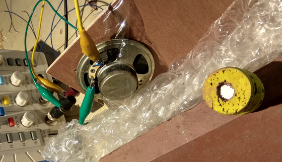
Another way of measuring the muzzle velocity is to use a magnetic projectile – a small NdFe magnet inside a cork would do – and a wire coil. As the magnet goes through the coil a momentary pulse of current is produced which is easily measured. In the picture below is a coil on a Vacuum Bazooka barrel. Also in a pic is a way of measuring via the noise of impact, using a loudspeaker as a microphone.
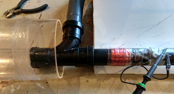
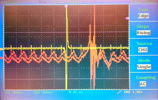
The last pic is an oscilloscope frame showing a first pulse due to a coil and a second pulse due to a loudspeaker microphone. With a spacing of 0.8m, you can figure out the muzzle speed to ~16ms-1, or 36mph.
You could also plot out the speed and acceleration of the projectile from when you let go, allowing for acceleration by the air pressure and deceleration by friction in the tube and by the covering paper at the end of the tube. You could put this along with a suitable model for how the tube pressure varies from the maximum partial vacuum to a minimum as the projectile compresses the air remaining in the tube. (In general, the remaining air is not sucked away fast enough by the vacuum cleaner.)
Finally, armed with the knowledge of the acceleration down the tube, you could redesign the launcher, perhaps employing a “vacuum accumulator” (simply a large volume connected to the barrel) to reduce the loss of vacuum as the projectile progresses up the tube. With a means of measuring muzzle velocity, you could then check how much improvement this makes.
References
Neil A Downie, Vacuum Bazookas, Electric Rainbow Jelly and 2 Other Saturday Science Projects, Princeton, 2001
Jones, D. R. H. Engineering Materials 3: Materials Failure Analysis. Oxford: Pergamon Press, 1993.
…
…
Vacuum Engines
I sell what all the world desires: power” —Matthew Boulton, pioneer steam engine manufacturer, partner with James Watt, Birmingham, 1780
Power is transmitted in everyday life most often by electricity. There are other means of power transmission such as high-pressure air, high-pressure hydraulic oil, and, on industrial sites, steam. However, electricity dominates: it is the most versatile form of energy. You can feel, to some extent, other forms of power. The rotating propeller shaft of a large truck leaves no doubt that considerable power flows from the engine at the front to the axles at the rear. Wander near a high-power electric system, and you’ll readily hear the low but insistent hum at the 50 or 60 Hz line frequency; sometimes you’ll even feel the hairs on your body react and of course huge and mortally dangerous flashes and sparks if cables are carelessly disturbed. Similarly noisy and spectacular gas jets signal the presence of even small leaks in compressed air or steam systems.
By comparison, the transmission of power through a vacuum in a pipe seems a peculiarly intangible concept. How can power be apparently transmitted by nothing? But in this project we show that a vacuum can indeed transmit power, and that we can demonstrate a motor rather like an old-fashioned steam engine, an engine that can turn the power transmitted by a vacuum in a pipe into mechanical energy.
The Industrial Revolution that transformed the Western world, starting about 1700, needed mechanical power. At first, increased use and more efficient designs of watermills and windmills could provide that power. But often the wind won’t blow or the water won’t flow. It became evident that continuous power was needed, and, less obviously, that steam could provide . It is easy to guess that you can get an expansive force from steam when you see a kettle boil. However, none of the early steam engines used that expansive power. Instead they used atmospheric pressure (they became known later as “atmospheric” engines), with the steam being used to create a vacuum so that the atmosphere could push a piston. The steam went through the pistons of the engine, and then out of the engine exhaust to a cold-water-cooled condenser, which converted the steam into water, creating a near vacuum. Here we call them, We might, perhaps less accurately, Vacuum Engines. Here is a short clip to show you a few examples: https://www.youtube.com/watch?v=wQNlXpmvMBk
There have been times when vacuum power transmission has been used. Perhaps the first example was the system used in Boulton and Watt’s factories in Birmingham, England. Engineer John Southern devised a system in which a steam-driven vacuum pump partially evacuated a huge pipe, known then as the “spirit pipe” and small and medium sized machines such as coin presses were operated by vacuum. Since the time of Watt and Southern, vacuum power has continued to be used in special places, such as in car brakes, and, interestingly, in some models of cylinder vacuum cleaners. In cleaners with a rotating brush, the brush is often powered by a simple turbine device that is turned by air flow to the vacuum cleaner’s fan which sucks in the dirt.
Our vacuum engine is a “steam engine” type of device. Unlike most steam engines, however, it does not require a fully equipped workshop with lathe, milling machine, and so on. Neither does the it need the thousandth-of-an-inch accuracy required of a working model steam engine. The vacuum engine only requires a few hand tools, pieces of wood, plastic tubing, and easily obtained metal hardware, and you don’t need to make anything more accurately than a millimeter. You won’t burn your fingers, either—because you don’t need steam! It is also easy to make—you can probably make one and get it going in an afternoon. Nevertheless, it well illustrates all the main working principles of steam engines: piston and cylinder, crank, flywheel, valve gear, and valve timing. Take a look at books like that of Semmens and Goldfinch below if you want to know more about steam engines.
What you need
- Vacuum cleaner
- Short section of 18 mm (¾ inch) hose
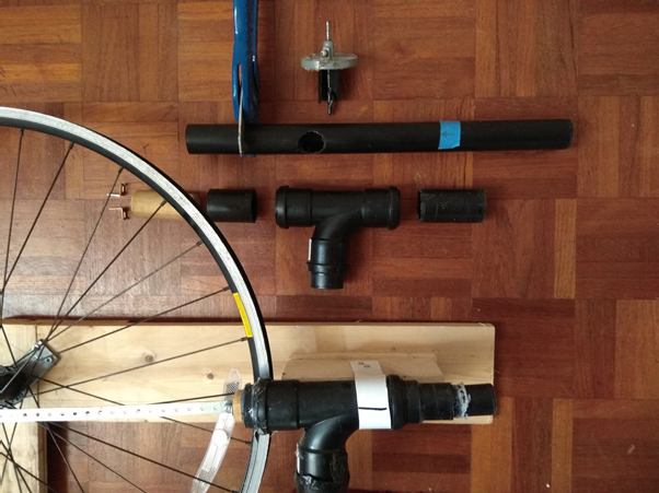
- 40mm Tee-piece
- hose or pipe with pieces of hose to connect piston to valve
- 30-mm-diameter round section of wood, and 35mm diameter, to fit snugly but free-running in 40mm pipe to make piston
- similarly 30-mm diameter wood for valve in 32mm pipe
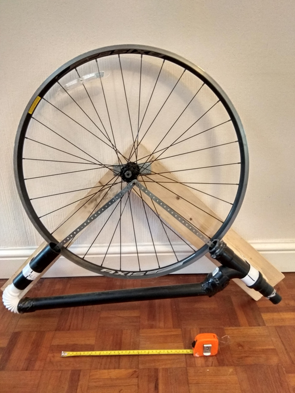
- Flywheel: pulley from an old washing machine, large circle of 15-25mm wood eg. 300mm diameter, or bike wheel
- Brass or steel rod for flywheel shaft that will fit the hole in the flywheel, OR, better ball-bearing which will fit to flywheel (or use bearings already on the bike wheel)
- fittings to attach flywheel shaft to wood frame
- Conrods (metal strips) eg. 8″ x 1/2″ Erector/Meccano set strips
- Wood pieces for frame
- bolts and nuts, hot-melt glue
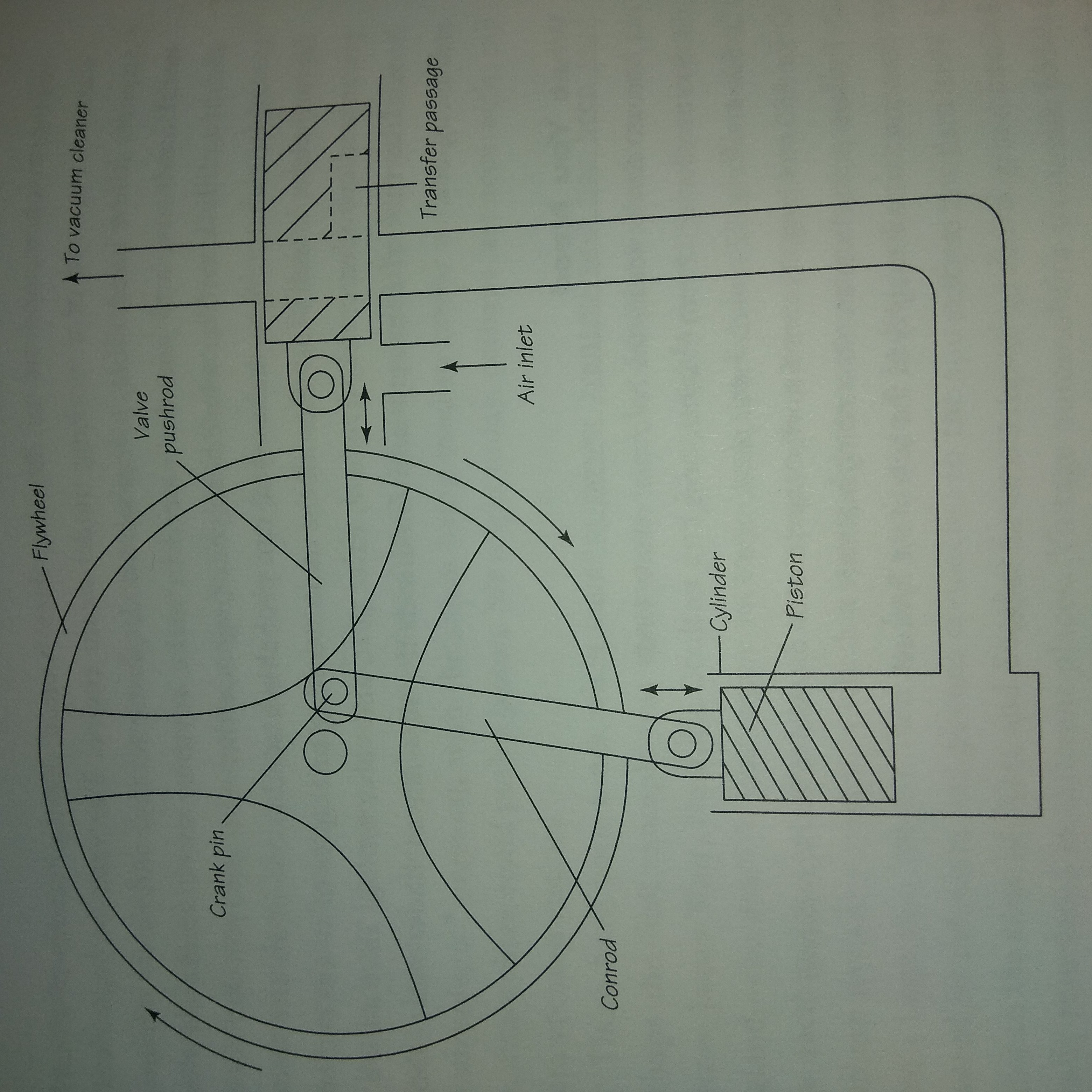
How to Build a Vacuum Engine The basic idea of the vacuum engine is that a piston is propelled up and down to push a crank that connects to a flywheel. The piston is activated by atmospheric pressure on its connecting rod (conrod) side, with periodic pulses of vacuum applied to its piston-head side. The pulses of vacuum pressure are applied by intermittently connecting the low pressure from a vacuum cleaner to the piston. The intermittent connection is made by a slide valve. The valve is synchronized to the flywheel rotation and hence to the piston movement, by being actuated 90 degrees out of phase with the piston in terms of flywheel position.
The power piston, once adjusted to the right size, needs needed no preparation at all other than to bevel the edges and to screw on the conrod bracket. The slide valve and its cylinder are more complicated. The cylinder needs two or three holes (an air inlet hole is optional) as shown in the diagram, which all need their edges smoothed. You must drill through the valve body for the vacuum port and then make a slot with a chisel for the transfer port. Glue pipe stubs to the holes opposite each other connect to pipes. The transfer port allows air into the drive cylinder after it has completed its power stroke.
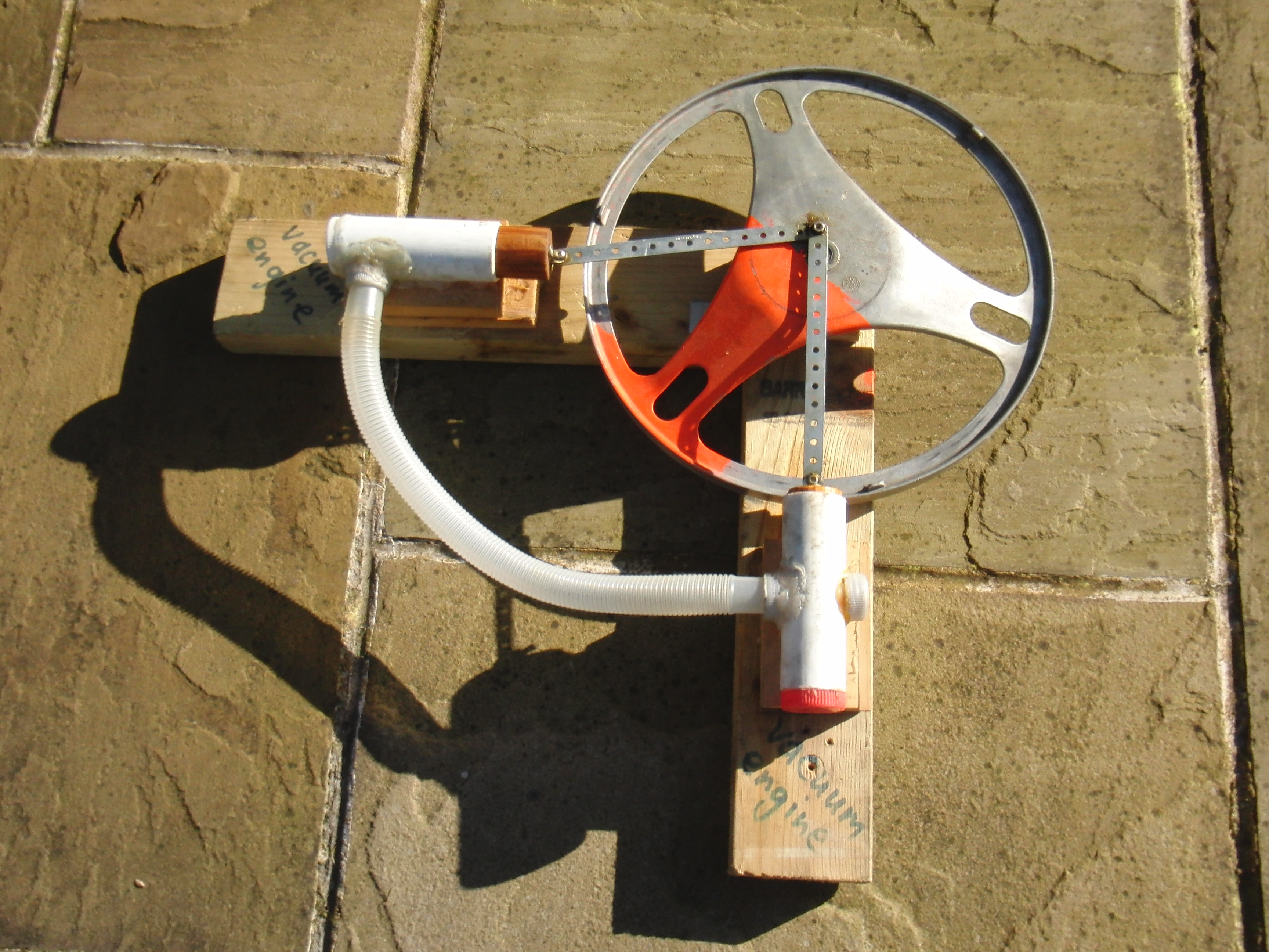
Early version of vacuum engine – dozens have been built since, right up to large bike-wheel size flywheels, and many using an improved valve design. The vacuum cleaner is connected to the stub on the right of the valve at the bottom. The working piston is on the left.

There are several alternative, simpler slide-valve designs: First, you can omit the air-inlet hole and the transfer port channel, and just rely on air leaking around the piston and valve. Second, you can omit the air inlet hole and transfer port from the valve piston. You can now switch the valve on and off with a simple cylindrical piston (exactly like the power piston), by arranging that the piston just uncovers the holes in the valve body as it reaches top dead center (TDC). Capping the end of the valve cylinder will help too, reducing vacuum loss and maybe reducing valve.
Thirdly, there is a neat way of making a valve which doesn’t involve gluing plastic pipe parts together to make an X-piece for the valve. Instead, you make a T-piece, with vacuum and piston going along the straight, and the vacuum out going on the side-arm of the Tee. That is a simplification, but, even better is that you can use a commercial T-piece to make the valve, which is much more robust.
Now having the valve-piston going in and out of a Tee isn’t as easy as it sounds, because the Tees tend to have a narrow part in the middle so you can’t get a piece of pipe (with drilled valve port) all the way through. Instead, put the valve port in a thinner piece of pipe, long enough to right through the Tee. This must be a fit inside the larger pipe which goes into the Tee. “32mm” pipe is ~36mm outside diameter, which is a good enough fit inside “40mm” pipe, which is ~37mm internal bore.
So put the port in the inner pipe, then cut the pieces of larger bore pipe and fit the latter to the Tee, then put the inner pipe inside the Tee. The ends of the pipes are sealed together at each end of the Tee once the port is in the right position in the Tee.
I used Erector/Meccano set parts to construct the crank plate and light steel strips for the conrods. The flywheel was attached with a grub-screw collet, as was the crank plate. The pipe work can be completed with a washing-machine drain hose, corrugated pipe, or partly with pipe and corrugated pipe. You can minimize the Erector/Meccano set parts and assemble a slightly simpler mechanism by making your own bearing for the flywheel and fitting the crank pin directly into a small hole drilled into the flywheel. The bearing for the flywheel can be made using a piece of 6 mm (¼ inch) steel and a piece of brass rod around 15 mm (⅝ inch) in diameter, glued with epoxy adhesive into the center of the flywheel central hole. Bore out the middle of the brass rod with a 6 mm (¼ inch) drill, deburr it if necessary with an oversize drill bit or maybe just with a sharp knife, then run the drill up and down it a few times until the rod will fit snugly but freely rotate around the 6 mm (¼ inch) steel rod. Alternatively, use a ball bearing, which will run with much less friction.
The position of the cylinder on the base plate is not critical. The position of the valve body, however, is more sensitive: it must just begin to open to vacuum when the piston is closest to the flywheel (the position conventionally known as top dead center, or TDC). You must ensure that every part can move freely. Check that the edges of the holes in the valve piston cylinder are smooth and that the pivots on the pistons and the crank are not binding. If rotated vigorously by hand without the vacuum applied, the engine should turn over at least three or four times. If you find that the engine slows more quickly than this, you should check for excess friction in one of the parts.
What You Do Without a plentiful supply of vacuum, your engine won’t work, so make sure that your vacuum cleaner has a powerful suction. The stronger the vacuum—meaning the larger the negative pressure relative to atmosphere—the better the vacuum engine will perform. If you hold any doubts concerning the performance of the vacuum cleaner, try to find some means of measuring the negative pressure it produces. The flow rate that the vacuum cleaner can produce is rather less important, as the flow rate needed by the vacuum engine is fairly low and, unless your fabrication of the device is more precise than I have suggested, much of the air flow will go to supplying leaks rather than to propelling the engine. If your vacuum cleaner has a low flow rate, you can still operate a vacuum engine, but you must make the piston and valve pieces a tighter fit within their cylinders.
Now position the flywheel just a little past the TDC. Apply the vacuum. With luck, you should find that the flywheel should begin to turn of its own accord, rushing down toward bottom dead center (BDC) and then beginning to slow down. But it should be going just fast enough to rotate one complete revolution at low speed, after which the process can repeat. The next time the engine will reach TDC a little faster, and the flywheel will complete its revolution more quickly. With the dimensions given here and a reasonably powerful vacuum cleaner, your vacuum engine should build up in speed until it is whirling around at 300 to 400 rpm or more.
How It Works The vacuum engine works by atmospheric air pressure. When the flywheel is at TDC, air pressure is the same on both sides of the piston, so no force is applied. With the flywheel turned a little, so that the valve opens to the vacuum, air is removed from the underneath of the piston. With no air pressure below but atmospheric air pressure above, the piston is forced downward. Curiously, in the engines we have tried, as mentioned above, the rather rough-and-ready fit of the wooden piston to cylinder may help, in that the air inlet and the transfer passage in the valve gear often do not seem to be necessary.
Troubleshooting Like the 18th century steam engines on which it is based, your vacuum engine may need a little adjustment before it will run properly ! You do need to ensure that all parts run smoothly and are lubricated with a little light oil such as bicycle oil.
The highest friction forces, assuming that all your components are smooth running under freewheel conditions, are on the slide valve, when vacuum is applied. With a fairly close-fitting slide valve, this force will be reasonably low. If, however, like me, you started with a rather loose-fitting slide valve, you will find that it tends to bind. What is happening here is that the valve piston is being pushed sideways hard against the valve cylinder because of air pressure on the side opposite the vacuum cleaner connection. Some oil may fix the problem, but if the fit is really loose, then make another slide-valve piston, one with a better fit.
The Maths and the Science
The easiest way to understand the engine’s cycle mathematically is by plotting a sine wave to represent the piston and the valve-gear positions. Once the engine has turned about 45 degrees past TDC, the valve begins to open and vacuum is applied and the engine will be forced around by atmospheric pressure until it reaches about 140 degrees past TDC, when the vacuum will be cut off once again and leaks will refill the piston/cylinder chamber, allowing the engine to run relatively freely past BDC at 180 degrees past TDC, and then freely to TDC once again.
Note that power is only being applied to the piston for 90 degrees of the 180 degrees past TDC for which power could be usefully applied. By readjusting the length of a valve rod or the width of the valve slot, you could extend the period over which power is applied. You could even extend the valve opening to a bit before TDC, because once the engine is running fast it will not be stopped by a momentary reverse force each cycle, and this will ensure that the slide valve is more fully opened during the power stroke.
We have thus proved that “nothing” can transmit power. But what “pressure of nothing” is best? What is the optimum pressure for transmission of power? A pipe will not transmit much power if the pressure inside is very close to atmospheric pressure: in the limit, when pressure is equal to atmospheric, there is no differential pressure drive, and no power would be transmitted at all. So the optimum pressure must be lower. At the other end of the scale, the power that can be transmitted at very low pressures must be low too: at an extremely low pressure, the mass flow through the pipe will be greatly restricted. In an ultra-high vacuum, almost zero mass of air would be moved along the pipe, and almost no power could thus be transmitted. The maximum amount of energy that a vacuum pipe can transmit occurs, therefore, when the pipe is at intermediate pressures.
The energy Ecomp stored in a compressed gas that is expanded from pressure Pi and volume Vi to final pressure Pf and final volume Vf is given by:
Ecomp = PiVi loge(Pi/Pf)
If we assume that the pipe is at absolute pressure P, and that the flow rate is Q, then the power transmitted in a vacuum pipe is governed by what we might call the vacuum engine transmission equation:
Pw = PQ loge(Pa/P)
where P is the pressure of supply and Pa is the atmospheric pressure. On the basis of this equation, the power transmitted, Pw, increases linearly with the flow rate volume flow rate Q. However, the pressure dependence is curious: as P gets closer to Pa, the power transmitted will tend to zero with the logarithmic term, while as the pressure P tends to zero, the power also tends to zero, but with the linear term.
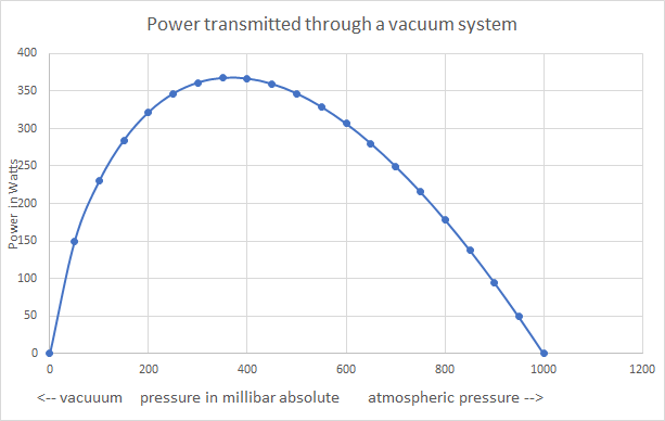
The plot in the accompanying graph contrasting pneumatic and vacuum power transmission shows that the optimum pressure from a vacuum source is about P = 0.4Pa. That there is a actually a value of vacuum pressure that is naturally favored for power transmission surprising result. Other power transmission systems have no such favored parameters. The voltages used in electrical transmission, for example, should be as high as possible. Similarly, the air pressures used in pneumatic systems should be the highest possible. There are also other considerations, of course, such as insulation and safety in electricity, and flow rates, pipe sizes and pressure drops in pneumatics.
If we compare vacuum power at the optimum 0.4 bar absolute with conventional pneumatic power at 7 bar gauge (8 bar absolute) using the same volume flow rates, we find that the pneumatic system will transmit nearly fifty times as much power. To reach a reasonably large power transmission with the vacuum system we need to use larger pipes giving larger flow rates. With laminar flow patterns, we might expect flow rates at a very low pressure differential, to depend upon r4, approximately, since
Flow = Area . v ~ v r2
where the mean stream velocity v goes as r2 for laminar flow. However, this formulation is unrealistic for our situation. For well-developed turbulent flow, so v ~ r, we will have
Flow ~ r3.
So, by increasing the tube radius by a factor of about 45 to the power 0.33, or 3.5, we should be able to provide the same power as a pneumatic system. The work done by a pneumatic system with 6 mm (¼ inch) tubing could be done by a vacuum system with 22 mm (⅞ inch) tubing.
Absolute and Gauge pressure Absolute pressure is the pressure exerted by gas molecules on a surface, proportional to the number of gas molecules per unit volume. No molecules = No absolute pressure. Absolute pressure measure is used in most scientific work. Gauge pressure is the standard engineering pressure measured by a simple dial gauge such as the Bourdon gauge. It measures the pressure relative to atmospheric pressure. Atmospheric pressure, which varies up and down by 3 or 4% according to the weather, is often given in millibar, 1000 millibar or one bar being standard atmospheric pressure. So a vacuum cleaner might have an absolute pressure on its tube or 780mbar, which is a gauge pressure of -200mbar, because it is 200mbar less than atmospheric pressure, if atmospheric pressure was 980mbar on the day in question.
And Finally . . . Spherical Balls and Pelton Wheels
You can experiment with many adjustments that might improve the vacuum engine’s efficiency enormously. Sealing the piston and slide valve more effectively to decrease leakage, or increasing the size of the piston and the slide-valve passages, will greatly increase the power generated. An air inlet on a vacuum engine that was well sealed would itself be a source of vacuum and could be used to operate another, lower vacuum engine; the combination would constitute a compound vacuum engine analogous to the compound reciprocating engines of yesteryear, with their multiple stages of steam expansion. The compound engine principle has been carried to even greater heights today in the turbines of aircraft and power stations, which can have a dozen or more stages, all crammed together or sharing a coaxial shaft. You don’t need to be restricted to a cylindrical piston and cylinder. What about using a spherical ball as the piston, for example? A spherical-ball piston eliminates the need for a “little end” bearing between the connecting rod and the piston, since the ball can be rigidly mounted on the top of the conrod.
How much power can you get from the vacuum engine? Could a “vacuum manifold” be used for powering engines in several different places? Or would the pressure transients due to one engine interfere with the running of another? Would similar engines on the same manifold tend to synchronize, rather like pendulum clocks on the same shelf ? Vacuum power is clean: it sucks away any contamination as it provides power. Could it be a useful power transmission system in the future, in places like wafer fabs or operating rooms where ultimate cleanliness is necessary?
References Semmens, P.W.B. and A.J.Goldfinch How Steam Locomotives Really Work. Oxford, UK: Oxford University Press (2000); Uglow, Jenny. The Lunar Men: The Friends Who Made the Future, 1730–1810. London: Faber, 2002.
…
…
Vacuum Railroad
I have no hesitation in taking upon myself the full and entire responsibility for recommending the adoption of the atmospheric system [vacuum railroad] on the South Devon Railway. Isambard Kingdom Brunel in a letter (in Adrian Vaughan book)
Elon Musk, the billionaire entrepreneur behind the SpaceEx re-usable space rockets and Tesla electric cars proposed a vacuum railroad which will run at higher speed than even the highest speed standard railroads. He wasn’t the first to think a vacuum railway was a good idea. I built vacuum railroads up to 6″ in diameter and put a kind of Vacuum Railroad in my 2003 book Ink Sandwiches, Electric Worms. But vacuum railroads / railways were invented long ago, and were briefly, the fastest vehicle on Planet Earth.
The vacuum-railroad principle was used for full-size railroads before being relegated to a role in conveyor tubes for mail and the like. In the most straightforward systems, a tubular train was simply sucked along through a tunnel or tube, as was tried in 1840’s New York. In a subtler variation seen several times early in the Victorian era in Britain, the carriage did not itself go down the vacuum tube. Instead a tube of 12 inches or so diameter was used; the tube had a piston inside and a slot along the top via which a metal fin connected the piston with the train, which ran conventionally on wheels on a track outside the tube. To avoid massive leaking of air into the slit, the slit was closed by a continuous simple flap valve that was held down by the vacuum itself. The valve sealed the slit except when a train came by. This was the technology behind Brunel’s system. Vacuum-railroad carriages were once the fastest vehicles on Earth: one of Brunel’s drivers was once accidentally pushed up the line near Bristol at 85 mph, the carriages having been uncoupled by mistake. Although a number were built and operated, some for many years, Brunel’s showpiece South Devon Railway was doomed by materials problems: the leather seal along the top of Brunel’s vacuum tube froze in winter, caused the iron plates to rust by retaining moisture[ , and was also eaten by rats! After a few years, the railway was closed.
The Vacuum Railroad we build here at first glance looks something like a the pneumatic money / small item delivery system sometimes seen in large factories and large stores, but using a vacuum cleaner for power.
To give you an idea, here is a video of a Vacuum Railroad we made on an Sunday – mainly with spare materials from a house building ! https://www.youtube.com/watch?v=yhye2eEJv7Y
What you need
- 4 or 5 plastic buckets, 2-gallon (10 liter) size or large
- 4 or 5 plastic buckets, 2-gallon (10 liter) size or larger
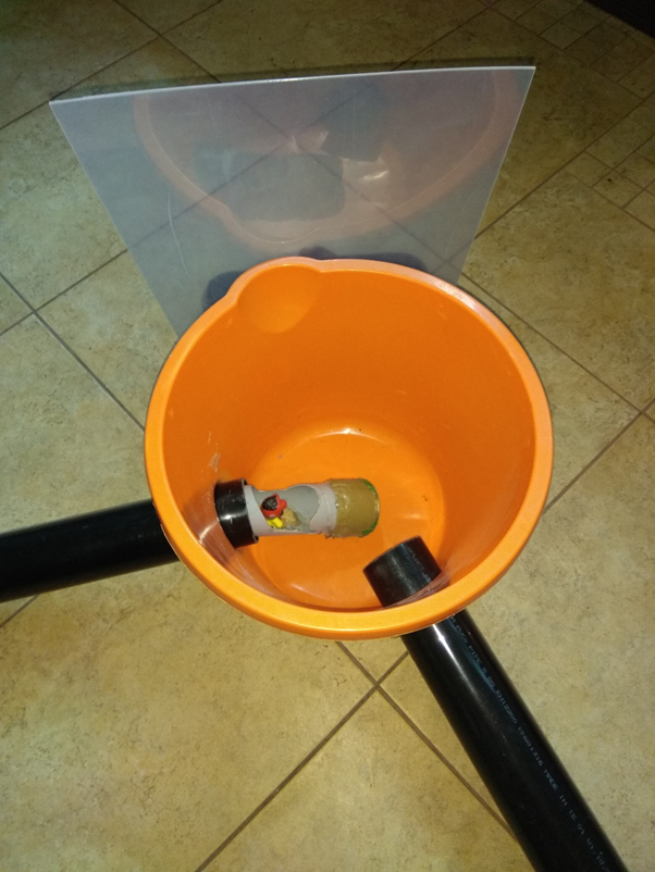
- 4 or 5 clear plastic lids to fit the above (e.g., pieces of “unbreakable glazing”)
- 15–20 m of plastic drain pipe
- 70 or 100mm (3 or 4-inch) diameter drainpipe
- or even larger, such as 110mm or even 160mm (but you will need a large capacity vacuum cleaner to run such a large size at a good speed)
- drainpipe T-piece to match drainpipe
- Cap for drainpipe, eg. flat piece of light plastic or metal lid from jar, large enough to cover end of pipe from T-piece
- Vacuum cleaner
- Vacuum cleaner hose
- short pieces of pipe one size smaller than the drainpipe (for cars of train)
- Cloth wrapping, eg. velvet, to make the seal around cars
What you do
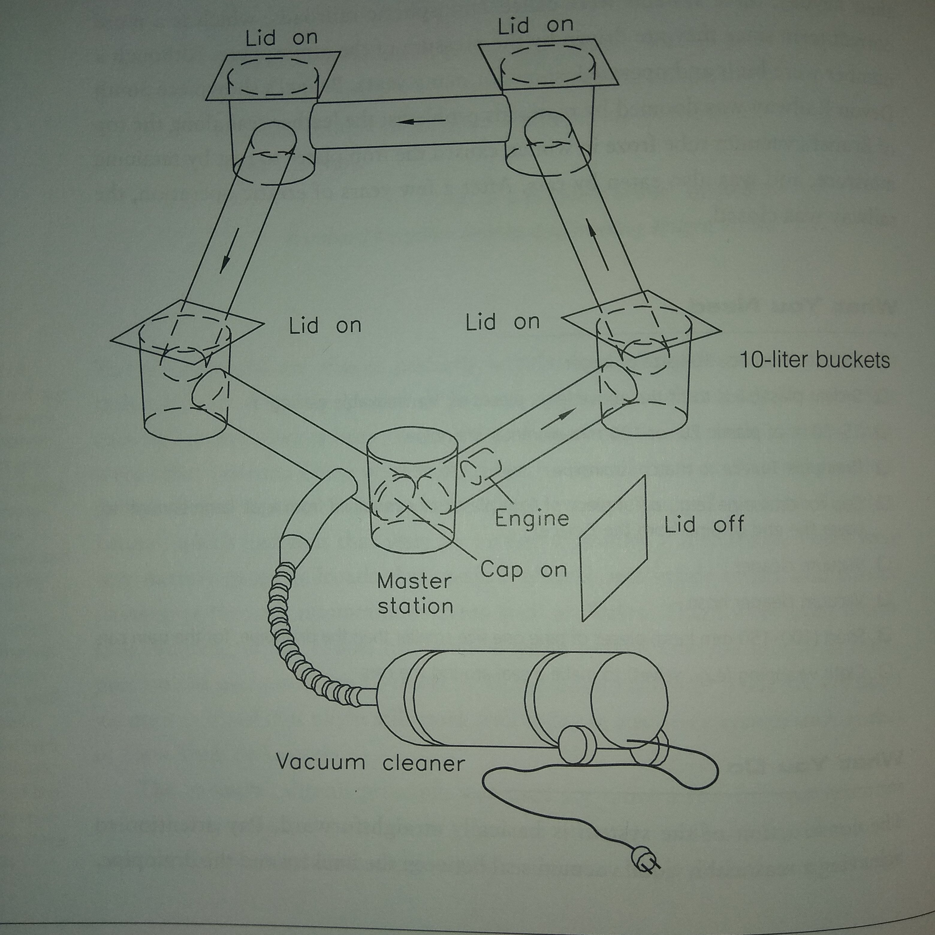
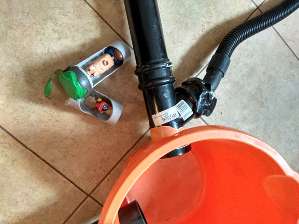
The first thing to do is to make holes in the buckets to match the pipe you are using. The construction of the system is basically straightforward. You need to achieve a reasonably good vacuum seal between the buckets and the drainpipe. You can just use a tank cutter to do this, and then seal the bucket-to-pipe joint with tape. You could maybe also buy suitable engineered ‘buckets’ made by drainpipe manufacturers, sold as ‘access chambers’, but these are expensive. However, I found that I could mark the area where the hole was required, soften with a small plumber’s blowtorch, and simply push a piece of pipe through the wall of the bucket at the appropriate place. If you do this, make sure to do this outside, wearing leather gloves, with buckets of waters handy (to extinguish any fire and to cool your fingers if you inadvertently touch something hot.) The result, if you do it right, is a hole whose edges stretch to form a conical skirt that blends smoothly with the pipe so that the whole system can be made to push fit. If any joint leaks significantly, a little duck tape should help – and, happily, the tape does not even have to stick particularly well. As in the vacuum is increased, the tape will tend to pull down and seal even better onto the wall of the pipe . But however you do it, you need buckets with holes, as shown. A simple rectangular track will require holes at 90 degrees, while a six-sided track 120, although of course you don’t need to make a regular track shape.
The vacuum cleaner is connected to the T-piece in the system, most easily by just using the vacuum cleaner’s regular hose, and sealing around it to the T-piece using well-compressed sponge rubber from packaging, using duck tape to finish off. The train can consist of an “engine,” which seals well against the pipe walls, and two or three “carriage’s” trailing along behind or pushed along in front. These can be as simple as a length of tubing, a loose fit in the drainpipe, perhaps with cut-outs to accommodate toy ‘passengers’. You can achieve a simple seal by wrapping the engine with a band of cloth – heavy velvet drape material is good – until you get a good fit.
The vacuum trains are completely enclosed and thus do not need Brunel’s slot-sealing mechanism. However, you do have to seal up the station the train is heading toward, otherwise vacuum will be lost. So the basic protocol for operation is as follows:
- 1. Seal all the bucket stations except the originating one
- 2. place the cap over the end of the T-piece pipe in the master station (where the vacuum is applied).
- 3. Push the front of engine into the tube.
- 4. Apply a vacuum.
- 5. Wait for arrival at the next bucket station.
- 6. Return to step 1 for the next stage of the journey
There is a subtlety to getting the train to arrive back at the master station . The T-piece allows vacuum to be applied to the system to propel the train into the “master” station, completing the circuit. Without the T-piece, the train could be drawn only toward and then into the master station and could not be propelled out of it. You might expect the presence of the T-piece to be a problem: Wouldn’t the train be sucked into the T-piece, where the vacuum connection is? This does not usually happen when the train is running at high speed because it has enough inertia to run past the T-piece and on down the short piece of pipe leading to the master station.
The Science and the Math
Maximum speed will depend upon the volume of air that the vacuum cleaner can deliver. The larger tube will have a greater force available, since the area over which the vacuum pressure applies will scale as the square of diameter. But with a large diameter tube, traffic will run slower because the volume of pipe will scale as the square of diameter. The vacuum railroad is capable of very high speeds. The acceleration, a, of the train is given by
a = ΔP (π / 4M) D2,
where D is the tube diameter, M the mass of the train, and ΔP the differential pressure created by the vacuum cleaner. The maximum velocity of the train, Vmax, is given by
Vmax = √(2La),
where L is the distance between bucket stations. Substituting for a gives the speed of the train as it arrives at the station:
Vmax = D √[2L ΔP (π / 4M],
which we might dub the “vacuum railroad equation.” Increasing the distance between stations, the vacuum pressure from the vacuum cleaner, or the pipe diameter will increase the speed of the train. The effect of diameter, being a direct proportionality, is greater than the effect of pressure or tube length. As you might expect, increasing the mass of the train will slow it down. The absence of a heavy locomotive engine allows the train to accelerate rapidly. With a 250-g train in a 3-m by 65-mm pipe and in the absence of friction or other slowing effects , the vacuum railroad train ought to be able to accelerate at 25 g. This will depend upon the vacuum achieved by your vacuum cleaner, of course, around 150-200mbar is typical. Furthermore, it ought to reach a final speed of 38 m/s, or 88 mph!
One problem with early tube railroads was that they used to heat up excessively because of friction. In long-distance mail systems, delivered trains would get up to such high temperatures that the guys who pulled them out at their destination had to handle them like hot potatoes. You might think you could avoid the heating problem, and the inefficiencies it represents, by using a looser seal, but then you have to consider the power losses associated with leakage around the seal. How much power do we actually lose to friction and leakage?
The total power Pdissipated is equal to the sum of P(friction due to seal), P(leakage), and P(friction due to weight). Can this total power be minimized? In engineering, there are often times when a compromise must be reached to optimize system performance. The optimization can be done mathematically. In one dimension, this process is straightforward using calculus. All you need to do to optimize a parameter like power is to find the calculus derivative with respect to the most significant controlling parameter, such as seal tightness and then look for a zero in this derivative. Finally determine whether it is a maximum or minimum, as desired, and—Bingo!—you have your optimum compromise. The compromise in our vacuum railroad is a fundamental one in engineering situations in which gastight seals are needed: tightening the seal increases friction, which wastes power; loosening the seal increases leakage, which also wastes power. Much engineering ingenuity is devoted to this quandary: great precision of manufacture is part of the answer, but there are economic limits to how far precision be carried. Low-friction materials for the seals and lubrication or both also can help. Pressure-actuated seals, such as the those designed around an annulus with a C-shaped cross section can also be helpful: the very air pressure that the annulus is sealing out is used to inflate it, pressing it harder against the pipe walls when the pressure is high and leakage through gaps would be great, and pressing it gently when pressure is low.
…
…
Vacuum Wall Climbing
We’ve all seen those movies where our heroes or superheroes climb up impossible-seeming walls – using handholds and toeholds a millimeter across, or actually sticking to the vertical surface. Of course its a simple cinematic trick. The ‘wall’ is horizontal and the camera is just turned around 90 degrees. But it need not be: it is possible, with the assistance of a couple of vacuum cleaners, to climb vertical walls. Sorry, coming soon…
