The credit-card sized BBC Microbit is an amazing little gadget. It combines a neat processor with simple on-line programming and a bunch of sensors. The on board sensors are for temperature, light, magnetic field in 3 axes, and acceleration on 3 axes. It can even use the magnetic field sensors as a kind of electronic compass. And on top of these marvels, it has a built-in 5×5 LED display and 3 easy to use analog / digital input/outputs and lots more input/outputs if needed. It has Bluetooth comms, and will also talk down the microUSB-to-USB cable used to program it from a PC or laptop. Millions have been used by kids in the UK and across the world. The addition of a Microbit to a project makes some things easier, but, crucially, it makes some projects possible that are almost impossible any other way.

The Electric Worm project was in one of my books, but only a few were made as described with control wires going to the Electric Worm, because it was crying out for on-board control which avoided the need for clumsy wires which could also confuse the behaviour of the beast. The Key finder isn’t easily made without a processor, and the Projection Clock uses not just the internal clock of the processor but also its intelligence to handle the mirror inversion of the numbers and the sensor of magnetic field to pick up a quartz watch or other time-piece as it pulses. Read on, and see how you can do some science and engineering and put your Microbit to work. (click on the links to jump down the page, or just scroll down, Home key to get back to top or just scroll up)
- Microbit Electric Worm #electricworm: a robot worm that relies on the curious physics of the Laws of Friction
- Microbit Key Finder #keyfinder: never lose your keys again – or at least if you mislay them inside a room
- Microbit Balloon Blaster #balloonblaster: Blast Balloons, one after the other, from the comfort of your armchair, with a laser or a ‘Photon Pistol’
- Microbit Ball Bearing Bobsled #ballbobsled Propeller propulsion and ball bearings instead of ice in this automated pushmepullyou bobsled
- Microbit Projection Clock #projectionclock: ever wake up in the middle of the night and wander what time it is ? With this clock, you only have to glance at the ceiling. But there is a catch – the numbers might not be English !
- Microbit Light Tunnels #lighttunnel : seeing light at the end of the tunnel turns out to be a turn of phrase that can be turned into a useful sensor for measuring angles.
- Escape Chute ! #escapechute Escaping from jet planes or ships in an emergency is important – and interesting. Here we use two Microbits, one measuring acceleration, the other acting as a radio station to record the data.

…
…
The Microbit Electric Worm
The laws of friction are not precise laws, like Newton’s Laws of Motion. But they are interesting, and despite their lack of precision still useful in many practical problems. The Electric Worm can move because it moves less than of its segments, or to be more precise, less of its mass, than it keeps stationary at any one time. https://youtu.be/hxyPGrggI8Y
Sorry, not available yet – but Coming Soon
Here we use a Microbit to control the movements of the segments.
A couple of Electric Worms spend a happy few hours crawling around the floor at the Houses of Parliament in London, thanks to an ‘Engineering Big Bang’ event for school students which was held in the conservatory of the HoP alongside the River Thames.
The Electric Worm moves by virtue of the laws of friction. They ensure that some segments stay put while another or others move.
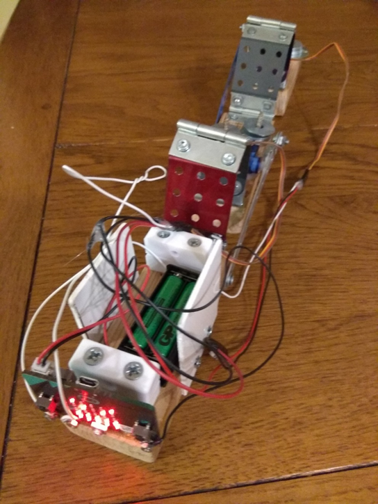
The Worm with 3 segments must move just one segment forward at a time, with the sequence running from the front via the middle to the rear segment, for forward motion. To move the middle segment, two servos have to operate simultaneously, as seen in this simple demonstration program, which moves the servo angles and displays the segment which should move:

…
…
The Microbit Key Finder
“Our life is a long and arduous quest after truth”
Mahatma Gandhi
My life is a quest after truth. But it also often involves a long and arduous quest looking for keys. We have all done it: put down our house key, car key or other valuable but small gadget, and then forgotten where we put it down. In a messy environment like a store room, or even in a tidy lounge, it is very easy to put your keys down somewhere where you can’t quite see them, or posed at an odd angle so they aren’t easily recognisable. The Microbit Key Finder is the answer to all our prayers: a way to find those lost valuables. Here we use the Microbit, attached to our keys, to beep back at us when it gets a trigger signal, so we can home in on the beeps and find the keys. But what signal can we use ?
A few years back, simple microprocessor electronics got sufficiently cheap that a viable key finder could be made which would allow you to whistle for your keys. These first key finders were based on receiving a whistle on a tiny microphone, then turning the microphone off and emitting a warbling beep. David Lander of the University of Strathclyde in Scotland filed a patent for a more sophisticated version of this, including a code to activate key finder units selectively using very high sound frequencies, ultrasound, in 1980.
Here, instead of sound, we use light as the signal to switch the audible and visible beacon. The later Philip Hall patent in the references first described this a while back, although I have never seen a device made according to the patent. There are similar patents from the Hewlett Packard company, although HP don’t seem to have made anything. But nil desperandum, you can make your own ! You just need to fit a Microbit with a sensitive light detector, and program it to flash the LED display and beep whenever a light signal is received.

What you need
Microbit
Phototransistor eg. Kingbright L-3DP3C 3mm infrared sensor from Rapid Electronics
100nF capacitor
Piezoelectric transducer (beeper). You need the sort that does not have a circuit built in to make a particular beep: the sort of beeper that is in effect a tiny loudspeaker. Almost any model of that type should work.
Battery box, batteries
Piece of wood or plastic to fix parts to
Croc clips or 4mm plugs
Wires, glue etc
What you do
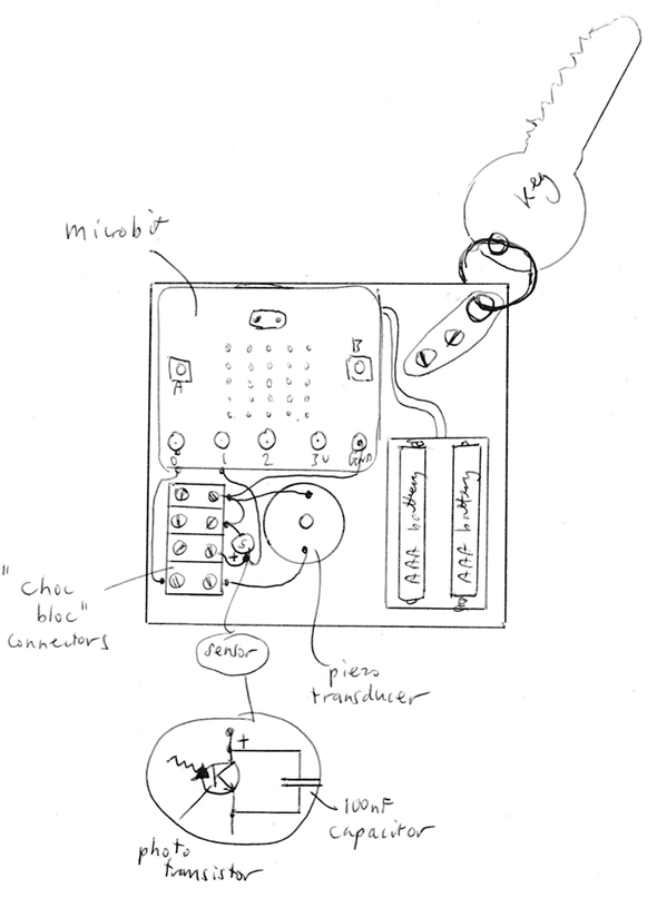
The phototransistor and capacitor must be connected to each other, and then the pair of parts connected to the P1 and ground terminals on the Microbit. The longer, positive, leg of the phototransistor must be connected to P1. This is our light sensing circuit, which has an inverted logic to it: the P1 voltage in fact is low in bright light, high in dim light. The voltage input to Microbit goes from 0 to 1023, representing voltages from 0 to 3V.
You will find that the voltages that you see due to the phototransistor will be, very roughly, as follows:
Sunlit room 6-9
Dull room 15-300
Room at night, lights on 350-550
Dark room 700-850
But check out what you get with your circuit, using the Microbit to measure.
The other pair of connections is needed from the piezo transducer to the P0 and ground (GND) terminals on the Microbit.
Finally, there is another component that we don’t need to add, because it is included in the Microbit itself. The Microbit has a resistor between 3V and the input terminal P1, which has a value of 10MOhms, so that a resistive device connected between P1 and ground will conduct a current of up to 0.3 microAmps.
The Circuit
The circuit we connect to the Microbit involves just two components: a phototransistor, and a 100nF capacitor. The phototransistor will conduct a small amount of electric current when exposed to light from about 400nm, blue wavelengths, to 1050nm in the near infrared.
The capacitor is suggested because artificial light mainly comes from mains-powered lights, and these, unseen by us,* blink on and off rapidly, 100x a second in places with 50Hz power, 120x a second in places with 60Hz power. The capacitor smooths out these variations and allows a fair comparison between light levels before and after the light is switched on and off to get the key finder bleeping.
*But you can see this blinking on and off if you look at mains-powered lights in a special way. Try looking in the dark at a distant or low powered small lamp, like an indicator, sweeping your eyes rapidly past the lamp. You will often be able to see a set of dark bands across that trace.
Programming the Microbit
It probably helpful to have an opening LED screen, an example is given. And the Button A input allows you to check that the light sensor is correctly connected to P1.
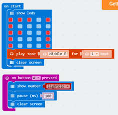
The fundamental of the program is that it must detect when the light level has changed. The input P1 is used for the voltage on the detector, and this is stored in the variable lightold. After 500 milliseconds, the program looks at the P1 voltage again and sees whether it has changed by more than a threshold value delta. The Abs instruction allows both upward and downward changes in light intensity to trigger the sound and light effects.
The value of delta is set to 10, but is reset to 3 if the P1 voltage value is less than 100.
Once the threshold is exceeded, we should flash the LEDs as shown. We also need to send the piezoelectric an audio-frequency current which will make it beep at the frequency that we want. The Play Tone instruction does this neatly, and the duration and musical note (frequency) is easily selected.

Things to Try
Once the hardware is connected and program installed, try the device out. You should find that with the device in a reasonably dark room (curtains closed if its daylight), the Microbit Key Finder should flash and beep when you turn the main lights in the room either on or off.
Check using the Button A function what values of voltage the light sensor is giving.
The values here in the program for the threshold, the minimum changes in light level input which triggers the alarm, are just examples. You might like to change them. Also, the switch of threshold from ten to three is the P1 voltage is below 100 (bright light) could be done differently, both in terms of what values to switch to, and what value of light level to do that switching.
Similarly, the 500 milliseconds delay could be chosen to be larger or smaller. The Key Finder is looking for a change with time. So, if the threshold is set to 10 units over 500 milliseconds, this is 20 units per second. So, logically, you could get a similar performance with a threshold of 20 units with a 1000 milliseconds delay, or a threshold of 5 units with a 250 millisecond delay.
The other obvious time constant to change is given by the value of the capacitor. With an effective impedance of (say) 5MOhm, the time constant for the voltage to change would be ~ RC, which is 5×106 x 100×10-9 = 500 milliseconds. If you make the capacitor too small, then it will not smooth the light variations due to the 50 or 60 Hz AC mains electric current.
You have probably found it useful to have the Microbit Key Finder operate both with decrease of light level as well as increase of light level. With an increase of light, you can look in full light for the device, homing on the beeping sound. With a decrease, you can look for the LEDs of the Microbit in the background darkness. What improvements could you make ? What frequency is the most efficient for the human ear to detect ? And could the LED flashing frequency be adjusted to make it more effective ?
The Theory: how it works
A phototransistor is an amplifier, just like a normal transistor. You put a small current into a transistor input (base) terminal and an amplified version of that current comes out of the output (collector) terminal. A phototransistor works a bit like a tiny solar cell connected to a transistor. When light shines on it, the solar cell part, the base-emitter junction, generates electron-hole pairs, which supply a small current, the base current. With voltage applied to the collector (positive) terminal, the phototransistor conducts a much larger current between the collector and the emitter (negative) terminal. The base current is increased by a factor, a characteristic of the transistor, signified by β or Hfe, which is typically over a 100.
As the collector-emitter current increases, it causes an increase in the voltage on the resistor built into the Microbit, lowering the voltage seen at P1, and this is how the ‘inverted logic’ of the sensor happens.
Why do we suggesting using a phototransistor sensor rather than the on-board light sensor in the Microbit ? The whole concept will work perfectly with the on-board light sensor, and this would make for a simpler project. However, it would probably not be sufficiently sensitive to work in typical indoor room light.
And Finally…
Taking the idea of using the on-board sensor further, why not try out a Key Finder based on it ? Outdoors it would be fine, but then you would have the problem of switching the sun on and off, although on a windy partly sunny day passing clouds could do this for you. Indoors, the sensor might work OK, using curtains or blinds to turn the sun on and off.
Light from a small ‘point-like’ source falls off in intensity with distance according to 1/R2 where R is the distance from emitter to receiver. This is one example of a 1/R2 law in physics. By taking a small source of light, in the dark, and seeing what output you get at different distances, allowing for the 1/R2 Factor, you should be able to draw up a proper graph of response versus light intensity for the sensor.
The phototransistor sensor suggested here is sensitive to near infrared light. Find a TV remote controller. They usually have an IR LED as their transmitter, and you should be able to detect this with sensor. Could this even make an alternative way of using the Key Finder ? One way to improve how this works would be to use an optical infrared filter: a black-looking filter, often included in the phototransistor moulding, which eliminates visible light but lets through near infrared light around 1 micron in wavelength.
What further ingenious improvements can you devise for the Microbit Key Finder ? What happens when you have more than one Microbit Key Finder ? Would it be useful to have a coded light switching, (as suggested by Robin Lander) so that you can activate only the key finder that you want to find ? That way you find the keys you want, not other keys. You could have 2 two pulses of light from dark for your keys, and three pulses of light from dark for your friend’s keys, four pulses for your sister’s keys, and so on. But how would you program this to wait until it might have received four pulses ? And how would it account for the different speed at which people put the light on and off. Or what about a Morse Code to activate the finder, where you just Morse Code your name or initials to get the finder to beep ?
References
US Patent 4,476,469 by Robin Lander of the University of Strathclyde
US Patent 6,579,258 by Philip Hall
US patent 6,911,909 by Ravi Chandar for Hewlett-Packard
…
…
The Microbit Balloon Blaster
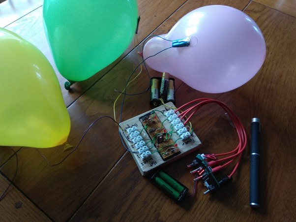
With a row of balloons in a room, what could be a more innocent happy pleasure than blasting them all with a laser ? You could use a laser which actually directly does that. But a laser powerful enough to do that would be insanely dangerous, not to mention seriously expensive. So here we use a Microbit as an optical sensor and as a sequencer to blow up balloons using a transistor pushing current through tiny blaster wires.
When it was invented in the 1960s, it was often said that “the laser is a solution looking for a problem”. Well, since then, lots of people have found problems that the laser is a solution for ! Lasers have been bounced off the Moon, cut through everything from diamonds to armour plate steel, and allowed the detection of gravity waves, alongside hundreds of other things. You may not realise it, but you probably have a laser or two in your house hidden inside things like a printer or a DVD player. You may even have a laser connecting your phone and computer to the Internet if you have a optical fibre connection.
In this project, we use a laser to blast inflated balloons. To do this directly by a laser would take a relatively powerful laser – maybe a watt or two of power – which would be very dangerous to the human eye. But we can do this safely with a low power laser pointer – milliwatts in power – by using a Microbit as an intermediary. The Microbit can detect when the laser beam hits it, and it can the blast a balloon by heating for a second or two a tiny piece of wire taped to the balloon. With several balloons, the Microbit can blast one each time the laser passes over its sensor.
How the Microbit detects light is unusual and interesting: it uses LEDs, light emitting diodes, backwards, as detectors of light instead of emitters. It has long been known, that LEDs are not just light emitters, but also photodiodes – light detectors – although it is very rare for anybody to take advantage of this possibility. Any photon (particle of light) of more energy than a certain minimum, the ‘band-gap energy’, will release an electron into the circuit connected to the LED. The band-gap energy is proportional to the energy of the photons that are released by the LED when it is used to emit light. So blue LEDs will work as violet light detectors, green LEDs will work as blue detectors, and so on down in photon energy, until some infrared LEDs will work as red detectors.*
*Forrest Mimms, the American amateur scientist, developed a number of simple scientific instruments using this fact. He made a simple spectrometers, relying on the different band-gaps of different colour LEDs, which can be used, for example, for monitoring the quality of light in the sky, indirectly monitoring cloud cover, water vapour and haze.
The Microbit uses this phenomenon using some of the LEDs in its 5×5 matrix display as a light sensor – that is the way its “light level” input works. Note that, as you might expect, the red LEDs are not very sensitive to red light, but need slightly higher energy light, which is why a green laser is suggested.
The best wire for making a small heater for the job of blasting the balloons is Nichrome wire. Nichrome is an alloy of nickel and chromium with some almost magically good properties: it is strong, elastic, melts at a high temperature, is a nice shiny silvery colour if not overheated and is highly corrosion resistant. More relevant here, however, is that it is almost a perfect resistor: its change in resistance with temperature is very small. (Most metals get higher and higher in resistance with temperature. Copper, for example, increases in resistance by a factor of more than 10x between room temperature and when it melts at a little over 1000 C.)
Copper also has the defect that it is simply too good a conductor. A conductor with a suitable resistance – say 1 ohm (giving 4 amps when fed with 4 volts, if you use Ohm’s Law) – would have to be impossibly thin or long. A 3cm piece of copper could have 1Ohm resistance, but only if it was 25microns (human hair thickness!) in diameter. Nichrome is almost 100x as resistive, so you can use a thicker wire, much more robust and easier to handle.
What you need
- Microbit
- Balloons
- Nichrome wire, Clear tape (Sellotape / Scotch)
- 3AA Battery pack, AA batteries
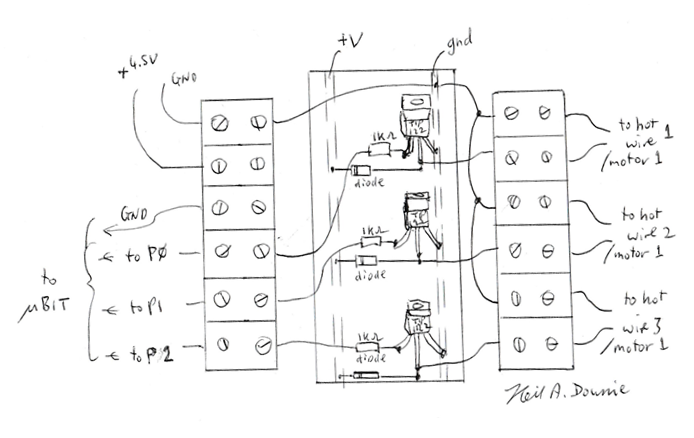
- For 3-balloon blaster circuit: Transistors (eg. 3x TIP121 or TIP122), 3x 1kOhm resistors, diodes (eg. 3x 1N4007), circuit board, hook-up wire, 2x 6-way choc bloc screw terminals, optionally 3x LEDs, 3x 220 Ohm resistors
- Laser eye-safe type, green is suggested, but any colour with energy higher than red should be OK.
What you do
The first thing to make are the blaster wires. These can be almost any wire, and can be simply a pair of standard low voltage ‘hook-up’ wire, as used in any electronic equipment. Thicker wire will allow you to place the balloons further from the blaster battery, however. The pair of blaster wires need to be connected to a short piece of Nichrome wire.
The simplest way to join up normal wires to Nichrome wire is just to bare the end of the copper wire and then to carefully twist the copper and Nichrome wires together tightly, perhaps curling it around after twisting to prevent untwisting, and then taping over the result. Make sure that no sharp wire ends can stick out of the tape to pop the balloon prematurely. You need 3cm, approximately, of wire, to give 2cm or so of free bare Nichrome wire.
The Nichrome wire can be soldered to a normal wire, which makes a more reliable joint, but you must a highly active flux. Soldering flux, normally a rosin-like (but synthetic) substance, allows soldering to take place by avoiding or even removing slight oxide contamination of the copper surface, allowing the solder to wet it. Most solder for electronics contains a minute core of flux, so that you normally don’t need to think about flux, but rosin flux is not active enough to work with Nichrome. For Nichrome, you can buy ‘aluminium’ solder, which has such an active flux built into it. Alternatively, use normal solder but buy a small tin of active flux.

You can test the blaster wires by taping one to a well-inflated balloon and
applying the 4.5-volt power pack to the wires by hand. You need to attach the blaster wires to
balloons with ordinary household Sellotape /Scotch tape, taping them on so that
the Nichrome was definitely touching the rubber skin of the balloon. You can bend the Nichrome a little to
guarantee this. It may be worthwhile to
tape them so that the Nichrome wire touches the balloon but without tape behind
it, over at least a portion of its length, because this will reduce the effect
of the tape cooling the wire slightly and allow faster blasting. It also avoids the problem that you might get
a whoosh not a bang.
The balloon should pop in a second or two when the current flows. Do be aware that the wire will get up to 300 or 400C, hot enough to give a tiny burn on your finger, so keep away from the wire when you are passing current through it. It will cool in less than a second to safe temperatures, but while current is passing it will be hot.
The Circuit
You can just buy simple drive circuits. Just make sure that they are suitable for high electric currents (several amps, depending upon the resistance wire you use). It’s better is to make your own, of course…
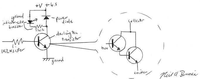
The circuit suggested is a simple transistor driver using a high gain Darlington transistor, with the current to the base (input) limited by a 1kOhm resistor. The diode is simply to ensure that if you change your mind what you want to do with the driver and want to use it on something which might generate a momentary high voltage, such as a solenoid or electric motor, it won’t blow the transistor. The layout diagram shows you how you might make 3 such circuits on a piece of circuit board, with the board and the choc bloc connectors screwed to a small square of wood.
Alternative to Lasers for Triggering Balloon Blasters : the Photon Gun

The photo shows a way of using a small torch, a bit of stiff wire (eg. from a wire coat hanger), and a hand lens for getting an entirely safe alternative to a laser beam for activating the Balloon Blaster. A powerful LED torch, its power concentrated by the hand lens, will do much that a laser will do. The choice of what distance to put the focus will depend upon the distance you will use to trigger the blaster. A sharp focus is not hugely important, however, as the concentration of power will still be mostly there quite a way from the focal plane.
Programming the Microbit
The program uses the light detection function of the Microbit, which, as discussed, depends upon the light sensor capabilities of the LEDs in its display. The LEDs which are sensitive to the light in the Microbit are those along the X-axis (top) and the Y-axis (left hand side). The light sensor command “light level” is in the inputs section of the Javascripts Block Editor.
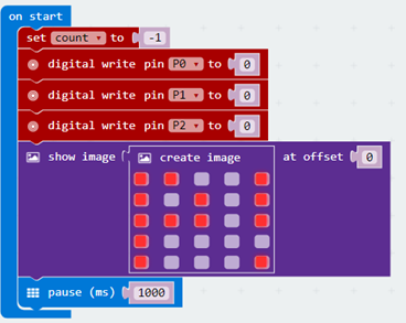
First the start up routine: the program should start with the balloon counter set to 0 and the outputs P0, P1 and P2 set to 0. But you might want to set the counter to -1, so that you can check that the system is working before you actually blast a balloon.
In running mode, the ‘forever’ loop, the system looks for a high light level on the input. Once the rise in light input has been detected, you need to output a current for a couple of seconds to blow the first balloon, then increment the counter. This will then allow it to blow the second balloon when the laser is used again and a rise in light input is once again detected. The laser pointer won’t raise the light level high for more than a few tens of milliseconds or so when its beam passes over the Microbit, and the person pointing the laser will see the number on the display go up and pause before pointing the laser again. But what would happen you did pause for longer with the laser ?

The change in the Microbit display gives instant feedback to the user that they were on target, unlike the Nichrome wire, which does take a second or two to act and explode the balloon. Without this, you would know whether you had activated the blaster or not until after the balloon explosion, which makes it difficult to use.
Things to Try
Time to try out the system. Take your trusty laser pointer, and take aim at the Microbit display.
Laser Safety: lasers can damage your eyes, even low power ‘eye-safe’ lasers. Never look at a laser directly, and look away from it immediately if it does point at your eye. Reflections are not usually as dangerous, but avoid looking directly at very bright reflections of a laser too. If you have doubts about laser safety why not try the ‘photon gun’ alternative suggested ?
The science of exploding balloons is surprising and interesting. A simple example: just inflate a balloon until it explodes from excess pressure. Now inflate a (similar) balloon to a good pressure and pop it with a pin. What are the differences between the fragments produced?*
*You will probably see a completely different pattern of fragments in the two cases, although the exact pattern depends upon the size, thickness, materials and other details of the balloons. The pure pressure explosion tends to produce ‘splat’ pieces, a central portion surrounded by jagged ‘fingers’. The pin-popped fragments are more regular in shape.
Slow motion videos of balloons popping are worth a look too – and if you have a high speed option on our camera you might be able to make your own.
Try different ways of taping the blaster wires. We rely on the fact that a tiny elongated hole formed by the hot wire will spread rapidly across the balloon due to the tension of air pressure inside the balloon. In fact the spread is rapid enough to go around the whole balloon in milliseconds, releasing the air pressure suddenly – the balloon goes Bang!
Critical crack length
The hole formed must be big enough, otherwise the balloon won’t go bang, but will just leak slowly through the tiny hole. The smallest size of hole that will grow is known as critical crack length. The effect intensively studied in connection with the accidental sinking of dozens of US designed cargo ships of a particular design called the Liberty Ship. Thousands of these were built under the emergency conditions of the Second World War. A number showed that once a crack was longer than the critical length the crack could run quickly around the whole ship, resulting in its catastrophic breakup and sinking.
Design changes, strengthening certain points to prevent cracks starting, and changing to less brittle steel alloy, eventually solved the problem. The critical crack length of a sheet increases with the stress on the sheet. So at low stresses, the critical crack length will be very long. But at sufficiently high stress, even a pinhole will grow to a catastrophically huge crack in milliseconds.
You may well have found out that if you tape the blaster wire on near to the neck of the balloon, you can get a serious anti-climax: the balloon can simply be punctured and deflate through a small hole with a little whoosh of air. Are there other places on the balloon where this happens? And, as already mentioned, if the wire is entirely underneath the Sellotape/Scotch tape, you can also get a whoosh not a bang. The effect is that the hole formed by the heat is reinforced by the tape, so that although it is stretched, even with a hole, the combination of balloon and tape is strong enough to resist the crack spreading.
A single balloon makes a satisfying bang when inflated sufficiently. The thicker the balloon skin the better, and the higher the pressure the better. But what about two balloons, one inside the other?
And Finally…
With a suitable app on your smart phone, you will be able to monitor the loudness of the balloons exploding. Do cylindrical balloons make a louder noise than round ones? Where is the best place to put the blaster wire on a cylindrical balloon?
What is the delay between triggering and the explosion of the balloon? You could measure this with the microbit itself, using a piezoelectric sounder, connecting it to ground and one of the Microbit inputs and writing a program which measures the time between trigger and a peak in the voltage. Test without a balloon by using a hand-clap, maybe.
References
Neil A Downie, Exploding Disk Cannons, p.18 “Balloon Detonator”
Neil A Downie, The Ultimate Book of Saturday Science, p.55 “Sunbeam Exploders”
…
…
Ball Bearing Bobsled
Still under construction – but read on if you like… The whole world goes around mainly thanks to ball bearings. Each bearing contains 10 or a dozen hardened steel balls which roll instead of sliding and let things go round with almost no friction. Your bike has probably got ten ball bearings: 2 in each wheel, 2 in each pedal, and a couple in the headset to allow the front forks to steer left or right. There are dozens around your house and in your car, hundreds in bigger vehicles, and myriads in industry. Similar bearings using little cones and cylindrical rollers are ubiquitous too.
Although 99 percent of ball and roller bearings are used in rotational motion, the same principel can be applied to linear movement. There are various designs that allow smooth and pretty much frictionless linear motion. They go into all sorts of applications too, from the mundane to the exotic, from filing drawers to high speed rowing boats like racing eights. The balls run confined to accurate linear motion in tracks, sometimes with a lightweight ‘cage’ around them to keep them accurately separated.
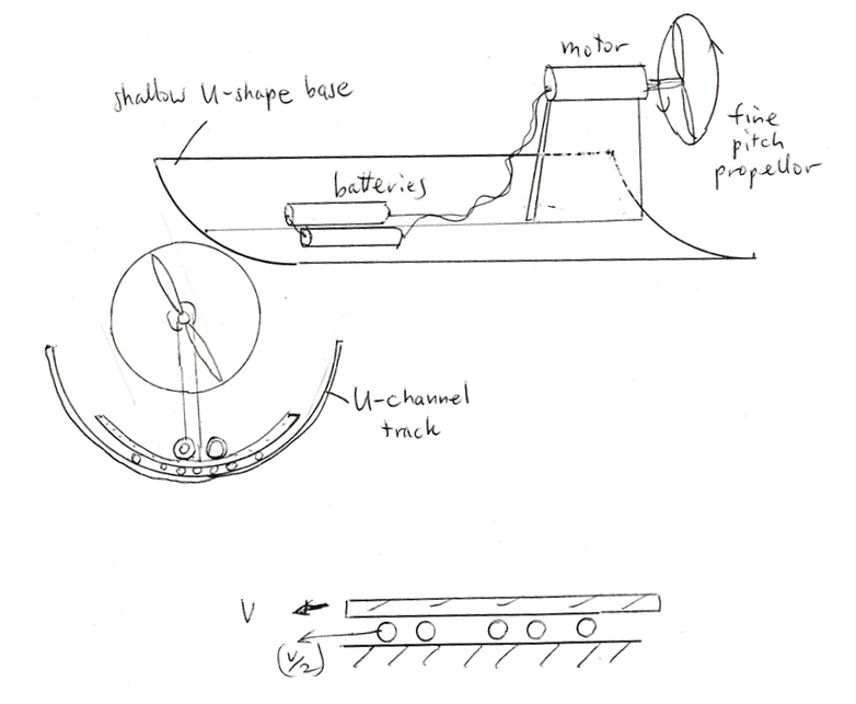
Here we take a simplified version of the linear motion ball-bearing (no moving, no accurate track for the balls to run in) for the vehicle. Our bobsled runs, not on ice, but on tiny glass balls. Various forms of air propulsion are possible, including a jet from a compressed air vessel, a ducted fan, or larger propellers.
With electrical propulsion and the Microbit on board, possibilities such as stopping at stations using magnets under the track and the Microbit magnetic field sensor. Or starting using an optical signal from a laser or a Photon Piston. A further level of sophistication is using two propellers and motors with two transistors to propel and stop the bobsled, allowing bi-directional service on track. This ‘pushmepullyou’ version uses a motor propeller unit on each end of the bobsled, facing in opposite directions. We can also deploy a BBC Microbit for sensing and data collection on acceleration, for example. Here is a short video clip on one version… https://youtu.be/_YAqnL4fEmg
What you need
- plastic half-round or U-channel, eg. 85 or 115mm wide and 3 or 4m or longer in length, as sold for guttering on houses
- foam for buffers at end of track
- small ( ~3mm diameter) round glass beads, the rounder the better !
- for ducted fan propulsion: piece of pipe to fit inside guttering + DC motor ducted fan + battery box / batteries / transistor /diode
- for propeller(s) propulsion: piece of pipe to fit inside guttering + (1 or 2x) DC motor(s), (1 or 2x) low pitch (eg. 5″ x 3″) propeller(s) + battery box / batteries / transistor / diode
- sundry accessories (see text) for Microbit functions eg. magnets, LEDs & sensors.
- for jet propulsion: soda bottle, tyre valve, tyre pump – no Microbit or other electrical parts required
- general items like wood or balsa, hot-melt glue, wires, solder etc
What you do
Soda bottle bobsled: Before working on a more sophisticated bobsled, its probably worthwhile to get hold of an empty soda bottle which fits the U-channel and try it it. The 2 litre size generally works well on 115mm guttering. Tape over the end of the channel so you don’t lose them, and scatter some glass balls in the bottom. You only need a small number – enough to form roughly a single continuous line of balls plus a bit – experience will tell you what is enough. Now try running the soda bottle up and down. You should find that you can blow the bottle along with your breath. Try blowing at the bottle in a bare piece of channel and you will find that it just won’t go.
You can make simple bobsled with its own power by drilling the base of a soda bottle to take a car tyre valve (details elsewhere on this website for doing this) and putting a pinhole in the screw-top. Heat a pin or needle in a small gas flame to make the pinhole, or use a miniature drill. Simply the pressurise the bottle with a tyre pump, while holding a finger over the pinhole. You may need to enlarge the size of the pinhole to get a powerful enough jet. Place the bottle on the channel and WHOOSH ! the air jet from the pinhole will propel the bottle along.
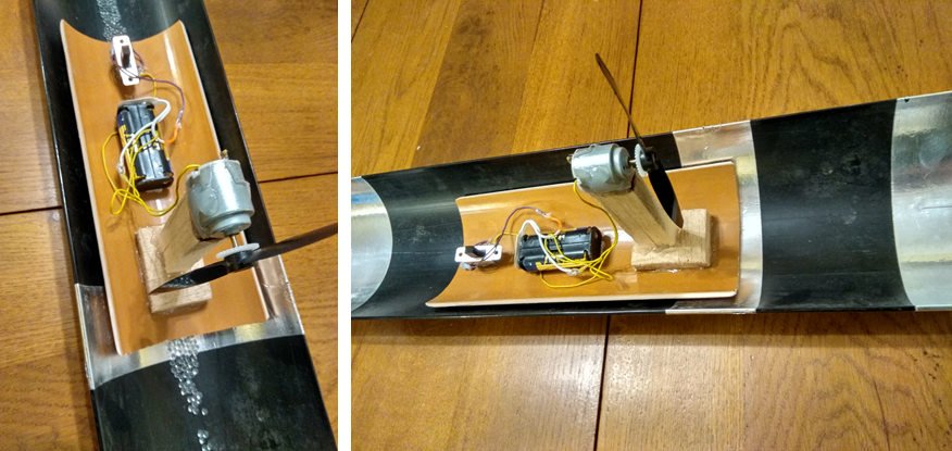
Electric Bobsleds: the simplest electric bobsled is made by fitting a motor and low pitch propeller on a short support or ‘pylon’ to a length of U-shape plastic which fits neatly in the U-channel. You need to put the batteries at the bottom, and make the motor pylon just high enough for the propeller to clear the U-channel plus a bit (to allow for the vehicle rocking to and fro). You need to be careful to avoid cuts on your hands from the propeller. Put the on/off switch at the opposite end to the propeller, and carefully remove any sharp ‘flash’ from plastic propeller, if there is any. You can also wear gloves, if you are using a powerful motor. The batteries going at the bottom is important to keep the centre of mass (or centre of gravity) low so that the vehicle is self-righting, i.e. it goes back to upright when the pylon displaced from vertical. The other thing worth doing with the electric bobsled is to add a foam buffer, instead of just tape at the end of U-channel – if your ball bearing bobsled goes fast, this will protect it from damage.
The vehicle body, the base, is probably easiest to make from a section cut from a piece of pipe. An alternative to the section of pipe is to use a piece of a soda bottle, which has the advantage of being lightweight. However, hot-melt glueing to the soda bottle can’t be done because the polymer (its PET, polyester) has been stretched in making the bottle and will shrink back to its original size when heated. You need to glue things to it with contact adhesive or use tape.
Electronic Bobsleds: with a BBC Microbit, you can log data on the motion of the bobsled. Set the Microbit on board transmitting data from the accelerometer data using the radio Send function. Then hook up another Microbit to a computer with a USB lead in the usual way, using on this one a On Radio Received function and then a serial write number to get data onto the computer. You could send all 3 axes of acceleration on the Microbit on board to the Microbit on the computer. Or you could just send a single axis of acceleration sensor output. These can be logged in a .csv file and then analyzed.
In a similar way, the on board Microbit can transmit other sensor data. For example, if you put a line of magnets down the track at intervals, you could transmit the magnet field sensor (X, Y, or Z or all three). By logging this data versus time, you can figure out the average speed of the bobsled between magnets as it goes down the track.
Controlling the Microbit Ball Bearing Bobsled
Motor connection: A BBC Microbit can be used to start and stop the bob using a simple transistor switch. The switch needs just a high gain bipolar transistor (‘Darlington pair’ or just ‘Darlington’). With an NPN darlington the motor is connected between the collector and positive, with a diode placed across the motor with positive end to positive (this protects the transistor and Microbit against power fed back from the freewheeling motor and its inductor effect. A 1k resistor in the base lead is also a worthwhile precaution, which will prevent an excessive current flowing from or into the Microbit in the event of some misconnection or other mishap.
Getting Commands to the Bobsled: you can use optical command via laser / or torch, perhaps using a ‘photon gun’ approach, as used in the Balloon Exploders project. The Microbit display LEDs can also act as an optical sensor via the Light Level input. Believe it or not, LEDs generally are also photodiodes. Although LEDs are not good photodiodes, this fact can be a handy dodge. You could maybe add with feedback from the display – check that display use doesn’t interfere with optical detection on Microbit. (This did happen with some versions of Microbit balloon blasters people have tried).
What about the details of control, you might be thinking. You could use one optical command pulse to start the bobsled to run for 5 seconds then stop. Or you could use one pulse for start, and the next one for stop. Or a long pulse for start, short pulse for stop.
Stopping the Microbit accurately at the end of the track without hitting the buffers, or at a station along the track is best done not by simply cutting the power to the propeller, but by using a short burst of reverse thrust. A reverse function can be provided by the idle prop in the pushmepullyou vehicle (below), or can be provided by a reversing relay on the motor, or by building or buying a bridge circuit, which can provide both directions of power to the motor.
Another form of command is more like a ‘driverless train’ – the future of railway transport, if some public transport pundits are to be believed. Fixed devices can be used to signal station zones along the track. Bands of reflective tape which can be picked up by a photodiode connected to Microbit, with ambient illumination or an on-board LED to provide the light which reflects off the track. Maybe easier is to use detection of station via magnet and Microbit magnetic field sensor.
Pushmepullyou Ball Bearing BobSled: you might want to make some kind of Pushmepullyou bob. With this, instead of putting the bob back on the track to go the other way, you can simply program it to reverse back to where it started: 2-way passenger service like a regular railway is within your grasp. One way of doing this is simply to reverse the propeller drive. however, this isn’t quite as simple as it sounds. A wrong-way round propeller works with only half or so of the efficiency of a right way round one – see picture. So a reversing motor propeller unit does not provide full speed operation in both directions. Also, as discussed above, a reversing motor drive is more complex than a simple transistor on/off control.
With two propulsion units facing in opposite direction, no reversing needed, so just two simple transistor switches can be used. Also, A wrong-way round propeller works with half the efficiency of a right way round one – see picture. So a reversing motor propeller unit does not provided full speed operation in both directions, unlike a pushmepullyou bobsled.
Props can be put on each end or maybe closer to each other both at one end. Don’t forget to make sure that the propellers are on the right way round.
How can you get forward and backward control as well as stop-start ? Just keep ‘flip-flop’ variable ? Or short and long light pulses, multiple pulses ?
The pushmepullyou vehicle provides in intriguing option for slowing down and stopping. As well as reverse thrust, you could use, at least for some of a stop, simultaneous forwards and backwards power to the propellers. Would this help in any way ?

Ducted Fan Ball Bearing Bobsled: An alternative to larger diameter propellers is to use a ducted fan unit, perhaps extracted from a hair drier (see Saturday Appliance Science). This can be convened with a tubular vehicle, like the soda bottle. Such a vehicle offers some new possibilities. Could it go around bends in the U-channel track, for example ? Should it be stabilized by significant weight like batteries at the bottom to keep it one way up, or would it be better to put weight at the centre ? And how an you make a pushmepullyou bobsled ?
The Science and the Maths
In any ball bearing, the balls move at a speed which is halfway between the speeds of the two sides of the race. So if the lower race is stationary, as here, while the top race, the bobsled here, is moving at speed v, then the balls will move at speed v/2.
This gives rise to a curious feature of the Ball Bearing Bobsled. Although it operates in an almost frictionless way, it still loses energy, ironically to the very balls that banish the friction. This arises because the balls are accelerated up to about half the speed of the vehicle, as expected, and the kinetic energy they acquire is then lost through the random vibration and jiggling of the balls behind the bobsled. If there are N balls per unit area, and the bobsled has area A, and each ball has mass μ, then the effective mass of balls in motion Mb is given by Mb = N A μ. With each ball moving at speed v/2, the kinetic energy Eb of the balls underneath the bobsled is
Eb = 1/2 Mb speed² = 1/2 N A μ (v/2)² = 1/8 N A μ v ²
At its speed of v, the bobsled, width W, will accelerate an area of (v W) of balls up to v/2 every second, so the mass of balls accelerated every second is Mb, where Mb = N v W . So, using Eb = Mb speed², we have for Pb, the power wasted in the kinetic energy of balls per second:
Pb = 1/2 N v W μ (v/2)² = 1/8 N v W μ v ² = 1/8 N W μ v³
We can check that this is plausible, of course (see Tips and Tricks) by using Dimensional Analysis. We can also think about the drag force on the bob due to the loss of energy, because Force x distance = energy, and Force x speed = power. so the effective drag force Fd on the bobsled due to the balls is given by Power/speed, or
Fd = 1/8 N W μ v²
This is the same v² law that we see for aerodynamic drag on projectiles, aircraft and, of course, vehicles of a more standard type. However, although this and the equation for power looks OK, there is a further complication, however. Rolling balls store kinetic energy not only in their linear motion but also in their rolling motion. At speed u, the kinetic energy of a non-rotating ball mass Ecm = 1/2 μ u², while the kinetic energy of a ball rotating at ω whose centre of mass is stationary is given by the analogous formula Erot = 1/2 I ω², where I is the ‘moment of inertia’. I is given by taking the integral of mass x radius² over the volume of the sphere, and is 2/5 μ R², for a sphere of mass μ and radius R. Now ω for a rolling ball is given by u / R. So:
Erot = 1/2 2/5 μ R² (u / R)² = 1/5 μ u²
So the total kinetic energy Eball is given by :
Eball = Ecm + Erot = 1/2 μ u² + 1/5 μ u² = 7/10 μ u²
So in other words, the rolling balls end up having an effective mass which is 7/5 x (1.4x) their actual mass. So in the formulas above, you need to put that in, giving, for the drag force Fd
Fd = 7/40 N W μ v²
And Furthermore…
The ball bearing system would appear to be intrinsically good with heavy loads: so what about a heavy weight Bobsled ? But how would you power such a sled ? And Furthermore…
References
This project first appeared in a different form (without Microbit enhancements) a while back in pages 107-112 of Neil A Downie Exploding Disk Cannons, Slimemobiles and 32 Other Projects for Saturday Science (Johns Hopkins University)
ω³²μ…
…
The Microbit Projection Clock
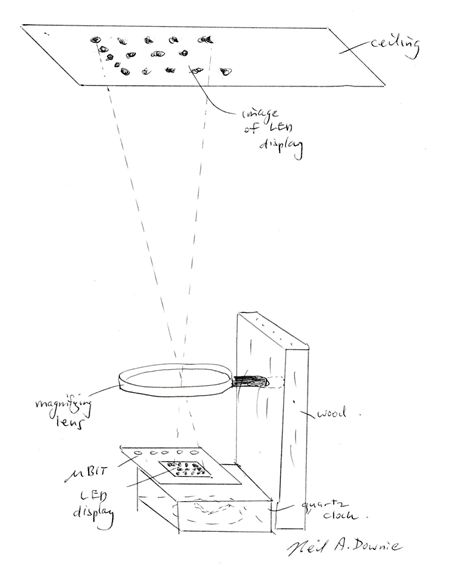
Here we use the Microbit LED display to show the time on the ceiling. The Microbit internal clock isn’t too bad. But we can make it much more accurate, as you will see. In principle it is easy to make a projection clock. Take an LED clock, put a lens in front of it, and aim it at the ceiling. But wait a minute… When you put an English character – or number – through a projection lens, it will come out upside down and a mirror image of what went in. How can we fix this ? And how can we use a clock which only can show only one character at a time like the Microbit ? Read on…
From ghoulies and ghosties
And long-leggedy beasties
And things that go bump in the night,
Good Lord, deliver us!
Scottish (traditional)
It is sometimes nice to know what time it is if you wake up in the middle of the night. Is it time to get up or was it just something that went bump in the night ? But if you have to mess around finding your watch, or switching a lamp on, this can make you wake up some more. And this is usually bad, because in the middle of the night you will mostly be trying to get back to sleep.
A projection clock is a great solution to this everyday – or everynight – problem. You just glance up to the ceiling, and there, in a pattern of tiny glowing dots, is the time. Middle of the night ? You can roll over and go back to sleep. 9:30, and you have lectures or a day at the office ? Start panicking and leap out of bed !
Insomniacs read on…
What you need
- Microbit
- Magnifying lens with low f-number (focal length / diameter ratio small)
- Analog quartz clock or watch (to provide accuracy)
- White ceiling or other surface
- Battery box and batteries, wood, tape, glue etc
- (optionally) USB power supply and USB to Micro-USB lead, to provide continuous operation
- (optionally) mirror eg. large size shaving / make-up mirror with flat side and magnifying side. The magnifying side should have a low f-number.
What you do
All microprocessors have a built-in oscillator ‘clock’ to step through the sequence of actions they do. And the Microbit is no exception. So you can use the built-in oscillator on the Microbit microprocessors as your source of timing for the projection clock.
However, the quartz oscillator technology of our clocks and watches is preferable. Standard quartz timepieces are very, very good. They measure time more accurately than we can measure anything else. A standard clock or watch is accurate to just a minute or two per year. That is just a few parts per million of error. That’s like measuring the length of a football pitch to a fraction of a millimetre. And an analog clock or watch emits tiny pulses of magnetic field as part of the motor that moves the hands. Thus In this project we could – with advantage – use a quartz clock or watch as the master clock to provide pulses of magnetic field. These pulses are then picked up by the Microbit and counted and displayed on the LED display panel.
A standard analog quartz clock or watch with rotating mechanical hands uses a synchronous motor as the prime mover, gearwheels then stepping down the rotation of the motor down to once a minute (for the seconds hand), once an hour (for the minutes hand), and twice a day (for the hour hand). In this project we use loops in the program of the Microbit to carry out the function of the gearwheels, while using further program instructions to display the results of the program ‘gearing’ on the LED display, in lieu of the rotating hands. We can use digital figures on the display, or we can mimic the dial and rotating hands of an analog clock.
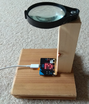
Finally, the LED display panel is placed near the focus of a lens which can then project the light from LEDs onto the ceiling or wall.
Quartz, Wonderful Quartz !
The quartz crystal oscillator is one of the most marvellous, ingenious and, despite this, cheapest, inventions of the 20th century.
You take a piece of monocrystalline silicon dioxide, more or less just very pure sand, and slice it in a particular direction. Then you cut tiny tuning forks out of that sheet of quartz. You now have a very, very good tuning fork. Ping it, and it will ring for 10,000 or even 100,000 oscillations. That’s very good. A musical tuning fork at 440Hz (middle C pitch) of that quality would be ringing for minutes, although quartz forks ring at 32kHz, so the length of ringing isn’t quite as long.
But this isn’t the only good thing. The modulus, the springiness, the ‘boinginess’ of quartz, varies very little with temperature. This is unusual: take a piece of rubber and warm it or cool it and you will see that its behaviour changes with temperature enormously : floppy when warm, boingy or even brittle when cold.
And there is another nice thing about quartz temperature behaviour: quartz doesn’t change much in length with temperature. Plastics change a lot with temperature. Metals change quite a bit too: that’s how a bimetallic thermostat works. And even glass, which is pretty stable, expands quite a bit when you heat it. That’s why if you pour boiling water into a glass vase it may shatter: the small amount of thermal expansion is enough to put it under tremendous strain and crack it. (Don’t try that experiment, it will be expensive !). Quartz, however, changes very much less even than glass.
The result of these two facts: modulus and length not changing with temperature means that the oscillation frequency doesn’t vary much with temperature either.
And as if this wasn’t enough, quartz has a further, very rare, property: piezoelectricity. A piezoelectric crystal works by converting a pressure and microscopic movement on its sides to an electrical voltage, or a voltage into a movement. By coupling the output of an amplifier to one side of a quartz crystal and the other side to the input of that amplifier, you can make an oscillator which keeps the quartz ‘humming’, oscillating continuously.
Each oscillation in voltage of the oscillator can be counted on a circuit. Now make the counter so that after every complete second (32768 oscillations) a pulse is sent to a synchronous motor. Then connect that motor via a couple of gearwheels to the hands of a display and you have a clock.
The Circuit
You don’t have to construct any circuit at all ! However, there are possible circuits that might be useful. You could, for example, connect wires of the motor pins of the quartz clock or watch to provide the seconds pulses needed. And you could use LEDs, activated by the output P0, P1 or P2, to be part of the display.
Programming the Microbit
One of the issues that arises immediately you try to display 5 characters on the Microbit (two hour figures, colon, two minute figures) is ‘scrolling’, the rolling of the displayed characters over the one-character ‘window’. The 5×5 LED display has only room for a single standard character, and in the normal way of things, you let the display scroll, using the software built into the Microbit operating system. Or you can scroll the hours, then (non-scrolling) colon, then scrolling minutes. But all this actually makes the clock relatively difficult to read, and perhaps distracting at night.
You could miss out the colon. But then how do you tell minutes from hours during the first 12 minutes of each hour ?
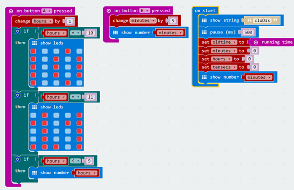
Below is a suggestion for a program which will get you going. The program looks at the Microbit’s built-in timer to get the passing of time, using the difference between successive readings from the ‘running time’ function in milliseconds. The alternative of using pulses from a quartz timepiece is further down below. The program gives out the hour, then, whenever 10 seconds have elapsed, it outputs the minutes, then checks to see if a whole minute has gone, when it updates the minutes. If the minutes get to 60, they are reset to zero and hours are incremented.

Counting up to 12 on the Microbit
The LED image command can be easily used to display the other numbers 10, 11, 12 without scrolling, and this is what is suggested in the program below. In this the hour is put up almost continuously, with minutes just flashed up on scroll every ten seconds.

This isn’t the only way to do it, of course. Most people don’t care most of the time what the time is to the nearest minute. The nearest 5 or 10 minutes is sufficient. You could flash up without the scroll just the tens of minutes, 0/1/2/3/4/5, along with a ring (signifying zero) of separate LEDs next to the Microbit connected to i/o port P0, P1 or P2 whenever minutes are up. You could even use those separate LEDs to do 5s of minutes, using the figure 5 and 0 on a seven-segment display.
Now set the program running and project onto the ceiling or wall. What do you see ?
Upside down ? So turn the Microbit around. Still not right ? instead of 0 1 2 3 4 5 6 7 8 9 are you seeing something like this or its the upside down version ?

Aaaargh ! What has gone wrong ?
It’s the lens, and it’s the fact that you are now ‘viewing the back’ of the Microbit in the image. The image from a convex lens is inverted from left to right and from top to bottom. Follow the diagram like that below in detail (and in 3D) and you can probably figure out what has gone wrong. Using two lenses, placed more than the sum of their focal lengths apart, you can get an image which is correct – but only if you have a translucent screen instead of a ceiling and view that screen from above – the opposite side to the Microbit.
You can just turn the image around to get rid of the top to bottom inversion, but you are still left with mirror writing. Maybe you can get used to reading this sort of digital clock. But there are solutions which make it easier to read.
You could take the software approach and program mirror writing into the Microbit, using the LED panel function, one for each number. Or maybe use two LED panels for 4 and 7 and letters /numbers for the other characters: 0 1 5 E ‘4’ S b ‘7’ 8 P . Or you could try a similar set of characters for the upside down version: b 8 L 9 S h E Z 1 0 which upside down looks like surprisingly good.
Optically right-way-round projected display
Alternatively you could take the optical approach and deploy a flat mirror to invert the image projected by the lens. The optical approach simplifies the use of scrolling clock displays, if that is what you want to try. The photo shows the sort of arrangement you will need.
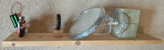
There is an even simpler optical arrangement than this, though, which takes advantage of the curved (magnifying) side of the shaving mirror. This acts as the equivalent of the combination of a mirror and lens above and also gives a correct image. This is trickier to set up unless you have a mirror which is significantly larger than the Microbit, and maybe the image won’t be as sharp, but it does work nicely.
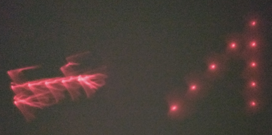
The photo below shows the difference between the very sharp figure ‘7’ from a simple hand lens on the right, and compares it to the ragged figure ‘1’ from a large shaving mirror on the left. Clearly the optical quality of a typical hand lens is much higher than that of a typical shaving mirror. Some of this may arise from the accuracy required in focussing mirrors: the allowable deviation from a perfect surface in a mirror is much smaller than that allowable in a lens. Try different focus distances, and try out using the mirror other than parallel to the Microbit. You can use the mirror to deflect as well as focus at the same time, although the quality of the image may decrease. Try different mirrors too: you may well find that short focal length mirrors are worse in quality than longer focal length ones.
Doing a clock-face display
An alternative to figures for the minutes part of the clock display is to mimic an analog clock display: a system of minute display which doesn’t involve scrolling the minute figures. Displaying the minutes as a bar graph, as given by the “plot bar graph” instruction in the LED commands works pretty well – and it doesn’t matter much which way round it is.
Even more sophisticated would be an LED version of a dial – as we use in the operation of the Microbit Combination Safe project: the LEDs on the edge of the display are illuminated one at a time. Although to be sure to be able to read it well, it would be worth illuminating a couple of LEDs in the middle to give orientation.
Getting accurate quartz time pulses from a clock or watch
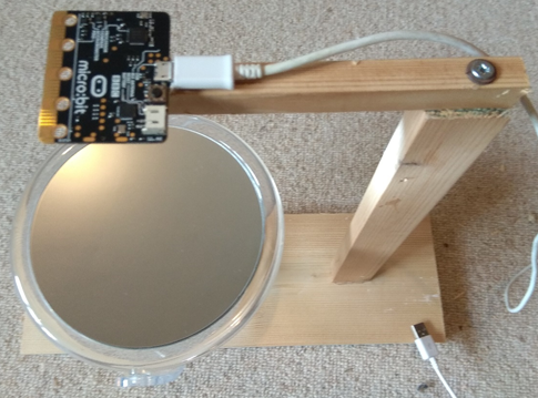
The program on the Microbit can use the magnetic sensor input to detect the pulses of magnetic field from a quartz timepiece. First use a simple program like the one below to get an idea of how much magnetic pulse you can get from your watch or clock, and also search for the best place on the timepiece to get the magnetic pulse. I found that I could get pulses of around 50 microTeslas from a standard quartz timepiece, fixing the Microbit compass (B-field) sensor near to the coil of the clock motor.

Once this has been done, the pulses can be counted. A logical (true/false) variable is used to indicated whether there is a pulse present or not.
The program below uses ‘hysteresis’. It requires that to detect a pulse you have to have more than 100 microTeslas, while to detect a pulse finishing there must be less than 80 microTeslas. The difference between these two thresholds is the hysteresis value, in this case 20 microTeslas. The use of hysteresis makes the detection of pulses much more reliable.
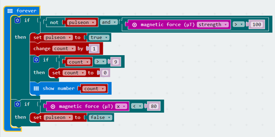
As before, after 60 pulses, the minutes variable can be incremented. And of course, after 60 one-minute pulses, the minutes go back to zero and the hour variable can be incremented. Otherwise, the program can follow the lines given above.
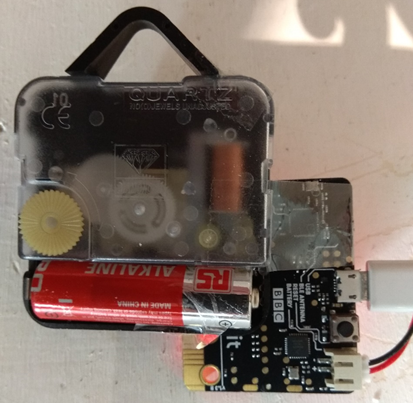
Above: positioning the Microbit over an analog quartz clock to detect magnetic pulses
Setting the projection clock
Of course, you need to have some facility to set the clock, otherwise you would have to wait until noon or midnight to set it going ! Here is some program to do that:
Things to Try
One thing you might try is de-focussing the LED image slightly. The image of each LED is very small. This is question of opinion perhaps, but I think the visibility of the characters is slightly better with the spots bigger. Another thing to try is shielding: at night, you may find the stray light from the bright LEDs distracting you from sleeping. Some dark paper or cardboard in a tube or cone around the wanted light beams will do the job.
If you are using the internal clock of the Microbit microprocessor via the millisecond ‘running time’ input, then you will probably need to adjust the timing slightly. For example, we found that one Microbit ran a clock program nicely, but ran about 15 minutes slow each 24 hours, about 1% slow. So instead of 10,000 milliseconds between updates, we used 9896 milliseconds, which pretty much fixed it, at least for that Microbit and for room temperature operation.
If you intend to make the Microbit Projection Clock a permanent feature of your room, why not plug it into a USB power supply ?
The Theory: how it works
First, just a reminder about focussing and what the focal length of a lens is. If you use a lens to focus a distant (in theory infinitely distant) bright object (like the sun, 93 million miles away), the distance between the lens and the image is the focal length, f. Now if the object is distance u away, then the image will form at a distance v which is further from the lens than f. The three distances are related by the algebra:
1/f = 1/u + 1/v
So, for example, with a focal length of 200mm and an object distance of 93million miles, we have:
1/200 = 1/∞ + 1/v,
1/200 = 0 + 1/v, so v = 200, which is what we said about the meaning of f above. Now take u = 222:
1/200 = 1/222 + 1/v
1/v = 1/200 – 1/222 = 0.005 – 0.0045 = 0.0005
So v = 2000mm in this case. Similar algebra works for mirrors too.
The projection increases the size of the characters formed by the Microbit LED display – obviously, right ? If the display is just 20mm across, and the display on the ceiling is 200mm high – you can measure them both with a ruler – then the magnification is 10x, right ? But magnification is a slightly more difficult concept than this. A microscope magnifies things, but you can’t get a ruler out and measure the image that you see. How big something looks to your eyes is what counts. In the case of the projection clock, consider the following. If you suppose that the Microbit is on a table fairly close to your head as you lie in bed, then how big the image on the ceiling looks doesn’t depend upon how big the image actually physically is. If you have a baronial bedroom with a ceiling 5 metres high, then the image will be 600mm high – but it will look the same as the image on a more normal 2m high ceiling, assuming that you don’t change the lens. The physical size depends upon the table top to ceiling distance, from 1.5m ‘normal’ and 4.5m ‘baronial’. If the ceiling is higher the image is physically bigger, but the size you see will be the same. The key factor is the ‘angular size’ of the image.
f-numbers of lenses
The f-number of a lens means that ratio of diameter divided by focal length. So a low f-number lens has a large diameter but short focal length, like Sherlock Holmes’ magnifying lens. While a large f-number lens has a small diameter but large focal length (like a typical telescope lens).
In this project, a low f-number translates into a smaller overall size for the projection clock, and a brighter image. With a smaller f-number, the lens or mirror creates an in-focus image when it is closer to the Microbit LED display, so gathering more of the light from the display.
It is difficult to make lenses of low f-number just using spherical surfaces. The focus starts to be lost as you go off-axis, which is dubbed ‘spherical aberration’, and even on-axis the focus is less sharp. At still lower f-number, you have to use multiple elements to the lens: two, three or four pieces of glass.
A glass lens with spherical surfaces, even made out of several elements, can only give you a limited advantage, however. For really low f-numbers it is necessary to shift to a lens using at least some non-spherical surfaces. This is where we are today, with low f-number lenses of extraordinary power and quality. What is more, these advanced lenses are so readily available that a mobile phone can be fitted with a lens which gives surprisingly good quality photographs.
And Finally…
More image inversion… Could you get the Microbit Projection Clock to illuminate the back of a translucent screen, like ground glass or greaseproof paper ? Would the images on the translucent screen still be mirror images ? Could you invert the projection by using two lenses instead of just one ? Or could you invert using a combination of a mirror and a lens ?
Brightness Control… You may find that the image projected is too bright, when the bedroom is completely dark. You could vary the brightness using the ‘set brightness’ command in the LED section. But maybe this is a problem in the mornings, when dawn light seeps through the curtains and now the ceiling image is too dim. Could you give your Projection Clock automatically varying brightness ? You could try the built in ‘light level’ input on the Microbit. However, if this is not sensitive enough, then you could try the phototransistor, as used on the Microbit Key Finder project.
Other Ceiling Information… Since the old days, when ceilings were painted with fabulous images like the famous Sistine Chapel, we seem to have forgotten to use our ceilings. What about other information that could usefully be projected onto the ceiling ? When you are walking or sitting, ceiling information needed for more than a minute is uncomfortable because our heads and necks are designed for operation in more horizontal plane. Viewing by a mirror is a solution to this problem, and a simple and modest sized mirror does the job. But as with the lens projection clock, you do then have to mirror invert the characters and images so that they look right in the mirror. But this is easily done. You could put caption information in museums and especially art galleries, clearing the space ahead to concentrate on the work or art or antiquity itself. But not only that, stations and airports could use their ceilings for travel information, avoiding the need for those annoying and difficult-to-hear Tannoy announcements. Ceilings need never be dull again !
References
US Patent 2,201,376 (1938) by Dutchman Leendert Prins.
Projection clocks have a long history going right back to the days of mechanical clocks, several hundred years ago. People in those days, if they wanted to know what time it was, and they didn’t live within earshot of a church or town hall clock bell tolling the hours of the night, had a tough time. You needed to light a candle, using a match (or, worse, a tinder box) – and remember, this is all in the dark – and then once lit, the candle could be used to check the dial of the clock across the room. You couldn’t have the clock next to your bed – it’s incessant tick-tock would keep you awake !
First to come along were ‘silent’ clocks, which replaced the traditional tick-tock with a quieter whirring of tiny cranks which pushed the pendulum or balance wheel to and fro. Then, for those who could afford to keep candles burning all night, a transparent dial with a candle behind it. There’s one like this in the British Museum. The advent of electricity allowed for simpler and better solutions like electric illumination and the synchronous motor clock, the mechanism still used today for switching things like street lamps on and off at regular times each day. Electricity also probably drove the invention of the first projection clocks. In 1909 projection clocks were built to a British Patent, using small lamps inside a cylindrical brass body. But it was not until the 1960s that projection clocks achieved popularity, first as analog dials, and later, in the 1980s, with digital images.
ω³²μ…
…
Light Tunnels
Take a length of flexible tube – it could be a piece of garden hose, for example, and look through it. See things at the other end, or just light reflected from the sides ? Now try bending the tubing, watching how the light changes. This simple observation can be developed into a useful sensor for how much a piece of tube has been bent, and, by extension, the angle to which two lengths of rigid material have been bent, if the tube is securely fitted to the two rigid arms.

asdf
A number of today’s sensors depend upon the measurement of the transmission of light through an object that is then related to the measurement needed. Medical applications often use this principle. Blood sugar tests used by diabetics often employ a small light-transmission meter together with a a piece of paper soaked with a reagent that reacts with sugar in the blood. The commonest medical application of this principle is probably the pulse oximeter, the gadget that clips onto your finger or earlobe and gives both your pulse and the level of oxygenation in your blood, both of which are vital parameters in medical treatment. The pulse oximeter uses two different light emitting diodes (LEDs) infrared and red visible, and measures transmission of both. The amount of transmitted light changes from moment to moment because blood flows in pulses driven by the pumping of the heart.
The light tunnel sensor in this project is another application of the principle of measurement via light transmission that—although not used widely, if at all, today—actually works particularly well. We’ve all used the expression ‘seeing the light at the end of the tunnel’. In this project we use the light at the end of the tunnel to useful effect, to produce an optical or electrical output that allows us to sense angle.
What You Need
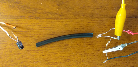
- Opaque tubing (e.g., 40–100 mm of black tubing, 5mm internal diameter, ideally not too thin a wall.
- LED or IRED (infrared emitting diode), 5mm or less in diameter
- 1 or 2 resistors, see text.
- Glue
- Resistor to limit current to LED eg. 30 Ohms
- Phototransistor or photodiode, possibly with an infrared filter (or another photosensitive LED or IRED)
- Batteries, battery holders (e.g., 3x 1.5-V AA, 2x 1.5-V AA), wires etc
- Multimeter with low uA current range (for photodiode) or mV range (for phototransistor).
- Wood and hinges (or a plastic adjustable drafter’s square or protractor), or Meccano parts to make a hinged assembly as per photo.
- (Microbit Readout: Microbit with batteries and 3 connecting wires.)
What You Do: It is probably easier to use a phototransistor, feeding with a 1k or 3k resistor. But photoresistors work well too, as do photodiodes. Photoresistors can be displayed directly by the multimeter (no second battery pack required), as do photodiodes, although the latter will produce a smaller signal, just a few tens of microamps. The IRED or LED transmitter should be run at the recommended current for it, or a little less (eg. 10-30mA for a typical 5mm diameter package device). With a voltage drop of, say 1.5 V, a 10mA current will come from the 4.5V battery pack via a 300 Ohm resistor (a near value readily available is 330 Ohm).
Glue the LED and the photosensor to the ends of the tubing. I found that black hot-melt glue was perfect. If you use clear tubing or clear glue, cover potential light in-leaks with black tape. The tubing should not have too thin a wall thickness. With a thin wall, the tube will tend to collapse more easily when bent over a short distance and high angle. The LED can be fed with 4.5V 3AA battery pack, while the phototransistor can be fed with a 3V 2AA pack.
Now apply current to the LED and the photosensor and adjust the multimeter to a suitable scale. As you bend the tubing, the phototransistor output should fall progressively as the angle of bend increases.
Fastening the sensor assembly to the wood (or plastic protractor, or Meccano assembly as shown in the picture if that’s what you are using) with one end on each side of the hinge and measuring the angle on the hinge (or protractor) will enable you to measure the readout quantitatively. And if you already have a project with a hinged arm of some kind, then attach the Light Tunnel to that. The tubing can be held by twisted wire, or by tightly fastened tie-wraps, although be sure not to fasten them so tight that the tube distorts a lot. The tube should be fitted close to the hinge so that it follows the angle faithfully without pushing to and fro. You should find that the system works up to angles of 45 or 60 degrees without special attention. If you need the sensor to work to high angles, think about using thicker wall tubing, and using a slightly longer length, so that the bend is spread over a longer distance along the tube.
How It Works: The sensor works by largely preventing the reception of direct light by the photodiode, that is, by forcing the light to bounce at least once. The light transmission decreases with the number of bounces required for the light from the LED to reach the other end of the tube. You may find that the system also works if you use another IRED or LED instead of a photodiode as a light detector. Many LEDs are light sensitive, and since they are generally packaged in round-nosed, bullet-shaped plastic capsules, they can be conveniently plugged into the end of the tubing. You should ensure that the “band gap” of the emitter—the photon energy that it emits—is larger than the minimum photon energy required for the receiver (see The Science and the Math). Photon energy is highest at the blue end of the spectrum and lowest at the red and then infrared end of the spectrum. This means that you can’t expect to receive infrared light with a red-sensitive detector, or red light with a green-sensitive detector, but the converse in each case would be fine.
Because the current provided by the light tunnel sensor varies smoothly and is stable and predictable relative to the deflection applied, the sensor can be used as a feedback sensor for a servo motor. A servo motor, or servo-actuator (servo for short), is a device for providing a motion output under the command of an input that has a feedback sensor element. Servos of this kind are widely used in industry, but perhaps most familiar to the man on the street from model cars and planes. Control systems like that of a servo which use feedback are sometimes described as a ‘closed loop’ because a loop connects the servo output back to the input, and are superior to ‘open loop’ servos. You can soon see that a closed-loop control system if you try to move the output arm when it is sitting stationary with a constant input. The servo from being passive, will wake up and apply motor power to push back against your efforts. We tried making a servo using a gearbox moving a Meccano joint, using a light tunnel for feedback, and put the idea in my book Ink Sandwiches. But there are other interesting things that can be done with the Light tunnel sensor…
Microbit Adaptation of Light Tunnel: The use of a Microbit adds a whole bunch of options. Firstly, simply using the Microbit as sensor amplifier and digitizer or ADC (Analog to digital converter) is helpful. The inputs to the Microbit will sense from 0 to 3V in 1024 steps, thus each step is around 3mV. But this is just the beginning. The Microbit can transmit values over its Bluetooth radio link, or on a micro-USB cable to a PC or laptop computer, putting the data on a .csv file via a terminal emulator program for analysis on a spreadsheet, perhaps. Going back to the discussion above, however, the Microbit could be used as a programmable part of a closed loop servo system. It can operate a robot or crane arm, sensing the arm position using a Light Tunnel sensor and positioning the arm by powering a DC motor and gearbox or winch using a bi-directional ‘bridge’ FET power module. Below the picture shows the Microbit linked to a test rig prior to use on a Meccano project.
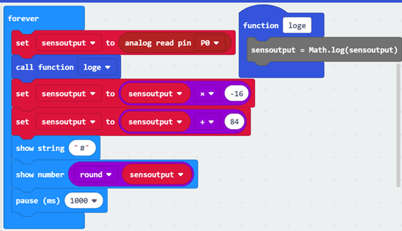
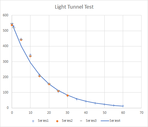
Linearization of the Sensor Output: Perhaps the neatest thing, however, is that the Microbit can be used to change the sensor output to an linear response to angle. The Light Tunnel is an example amongst legions in the world of sensors. Most sensors do not give an immediately useful output. Firstly, they often need a zero offset and a multiplying factor. Secondly, and more seriously most are not linear in their outputs. The offset, multiplier and linearization and any other ‘tuning’ of the output is best done by adding a microprocessor – like the Microbit. The Light Tunnel input needs to correcting using an offset and an approximately exponential curve, as the test graphs above indicate. The linearization of the sensor could also form a part of a servo control project: the Microbit can provide both sensor data correction and motor control. Below is a plot of the sort of response you can get from a light tunnel sensor:
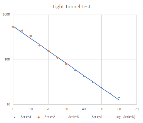
Re-plotting this graph, using log(response) versus angle gives an almost linear response:
Microbit Program: The program above shows how a simple exponential function can be programmed into using the Java facility inside the simple block program of the Microbit. The math.log function is in Java, and can be written into the function ‘loge’ of the Block system. The rest of the program uses the user-friendly Block editor, accessing an analog input pin0, then applying loge (ln, natural log) and then an offset and multiplier, of -16 and 84. The ‘#’ symbol separates outputs. Your sensor will have different constants, and may need slightly different maths – testing should reveal this to you. The math converts the voltage output from the sensor we tested to an approximate angle in degrees in the ‘sensoutput’ variable.
As suggested the Microbit can then be further programmed to send readings to a PC / laptop computer via USB or Bluetooth or used to control a servo.
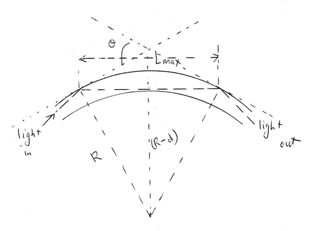
The Science and the Math: The light tunnel sensor works mostly by forcing the light to bounce at least once. The light transmission decreases smoothly with the average number of times the light bounces before reaching the other end of the tube. One way to quantify the operation of the sensor is to estimate the number of bounces needed to get from one end of the tube to the other. The maximum length, Lmax, between bounces is given by Pythagoras’ theorem:
(Lmax/2)2 + (R – d)2 = R2, or Lmax = 2Ö √(2Rd – d2),
where R is the tube radius and d is the tube diameter. For more typical bounce lengths, Ltyp, we might take d/2 as the radius:
Ltyp = 2 √[Rd – d2/4].
The deflection angle, q, for a tube with length Ltube is given by
q = Ltube/R,
so
R = Ltube/q, and Ltyp = 2 √[dLtube/q – d2/4].
If we estimate the transmission as the number of bounces, B, times the reflection coefficient of the tubing, taken to be approximately constant at 1 – a, a being the absorption coefficient per bounce, then
B = Ltube/Ltyp.
The transmission coefficient, E, is given by</eq>
E = (1 – a) B
For small numbers of bounces and small values of a—that is, when most of the light is reflected—we can use a slightly simpler formula:
E ~ 1 – aB.
This formula is correct within a couple of percentage points for values of E greater than 0.75. Of course, for large numbers of bounces and small values of a, we will see an exponential decrease of light transmission with distance along the tube:
E = exp(k/Ltyp),
where k is a constant and Ltyp is a characteristic length, related to the distance between between bounces. This equation takes the same mathematical form as the Beer-Lambert law for the absorption of light as it passes through a homogenous absorbing medium, the law used for calculating, for example, light transmission in medical pulse oximeters.
Our analysis so far has ignored the direction of light as it enters the sensor from the LED. It also ignores the change in reflection coefficient with angle (the coefficient will typically be large for small angles—which is why you can get such a good reflection from a piece of black glass). It also sweeps noncircular bending of the tube (which can be extreme – collapse or ‘crimping’) and a lot of other things under the carpet. It would be very complicated to take all these things into account.
Comparison of a graph of the exponential function with output-current figures from a real sensor shows a reasonable degree of agreement, at least for medium and large values of the deflection angle, q. The agreement is less for small q because we have failed to correctly account for what happens with direct light transmission when the tube is nearly straight. If you peer down a short length of tube and bend it, the initially circular disk of direct light will change to a leaf shape and gradually disappear as you continue to bend the tube, a bit like an eclipse of the sun in reverse. To account for the small-angle behavior of the light-sensor tunnel, we actually need something like an “eclipse equation”. Such an equation gives the relationship between the area of overlap, A, of two similar size discs of radius R (eg, the Sun and Moon as seen from Earth) and the distance, 2d, between their centers:
A = pr2 cos–1(d/r) – d √(r2 – d2)
Adding this shape to the shape obtained from multibounce formula above – and maybe other smaller bend effects – might give us an even good model of the sensor.
And Finally . . . Double Bending Light Tunnels: Some sensors that use something like the principle of the light tunnel have been proposed, although none seems to have caught on. They have been used for monitoring the angle of human limbs and fingers, for example, the Sayre glove. In 1985, Thomas Zimmerman patented a “data glove,” that used flexible sensors to allow hand movements to be input to a computer in a virtual reality system. Zimmerman also proposed complex arrangements of colored LEDs and multiple, or multiplexed, detectors, which might be able to sense movement in different directions of bend. Maybe you can devise a simpler system for sensing the degree of bend in two planes, say theta and phi deflection angles, using a single tube.
Better bending: Alternatively, you could just try to make our simple sensor work better. The mechanical characteristics of elastomer tubes change slowly with time. Unless natural rubber, for example, is heavily protected with an antioxidant, it will lose strength and elasticity with age. Synthetic rubbers may be more durable. Plastic tubing mostly works well, but plastics will undergo “creep,” to a much greater extent than do elastomers: they will tend to slowly mould themselves into their new positions, adopting a curled shape if they are left for a long time in a curled posture, or adopting a straight shape if they are left straight long enough. Paying attention to the mounting of the tube will help to mitigate the effects of creep but will not entirely eliminate it. Finally, on tubes, how could you encourage the tube to bend through large angles but without the tube collapsing ? After all, the human elbow, to give an example of a joint we all know, moves through far more than 60 degrees – more like 160 ! Could internal reinforcement do it, without messing up light transmission ? Or would external reinforcement, which definitely not mess up the light path be better ? But how can you do external reinforcement ? Take a look a pipe-bending machines for inspiration.
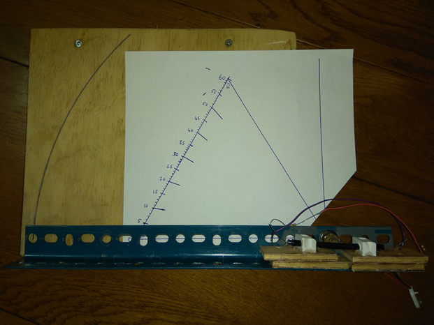
test light tunnel sensor on Dexion joint with customized triangle protractor
It is not necessary to use an electrically driven light source at both ends of the tube. You could use ambient light, or you could pipe light in with an optical fiber. And the photodiode could be replaced by an optical fiber pickup. When both the sensor and the emitter are optical fibers, we have the opportunity to mount the sensor in a hostile environment since, within limits, pressure, temperature, corrosive liquids, electromagnetic interference etc will not affect the optical fibers.
References: Webster, John. G. Design of Pulse Oximeters. Bristol, U.K.: Institute of Physics Publishing, 1997.
Zimmerman, Thomas G. “Optical Flex Sensor.” U.S. Patent no. 4,542,291, September 17, 1985.
ω³²μ…Δ
…
Escape Chute !

Escape chutes, sometimes called escape slides, or emergency slides, or evacuation slides, are fitted on jet planes and ships for the rapid evacuation of passengers in the event of an emergency. They are very rarely used – but when they are, they have to work well.
Escape chutes are typically inflatable, to save cost and weight, and follow a decreasing sloped curve through the air when in use. The steeply sloping slide is familiar to 99% of passengers because of their experience in playgrounds, of course, but there are also vertical escape chutes, and this is what we tested first below. They are needed because aircraft are raised quite a long way from the ground, typically, while in ships there may be 10 or more decks above the water line – 30m or so – for passengers to descend to the sea surface. They are used, although rarely, for fire escapes in buildings too, when they may be very large indeed.
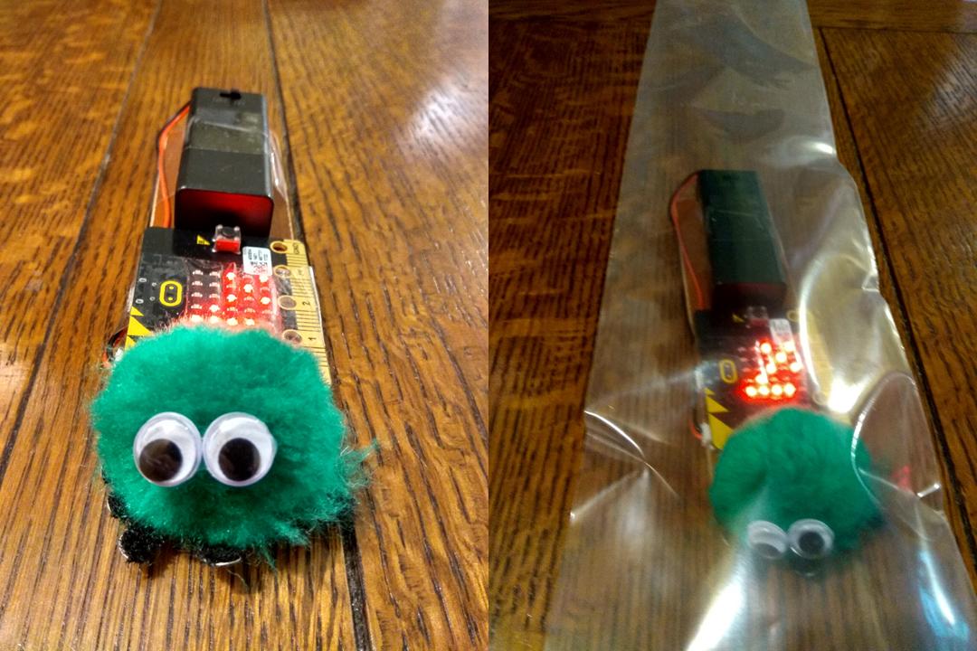
What you need
- Microbit + battery box
- thin piece of wood
- long strip of tubular plastic film eg. as used for heat-sealed wrapping
- head, eg. green furry bobble creature
- stairwell or similar longish drop (more than 3m)
- cushion (to prevent injury to ‘escaping passenger’
Make a escapee guinea pig like Ginny in the picture. Or maybe you could use a small human model such as are sold for artists’ drawings. Ginny is glued to a thin slat of wood to which is glued a Microbit and batteries.
Setting up and programming the Microbits
The transmitter Microbit on Ginny must measure acceleration. There needs to be a timer set to repeat the measurement sufficiently often. In the first instance, maybe just use one acceleration vector components, X, Y or Z, or perhaps the vector magnitude. These data must then be radio transmitted to the second Microbit.
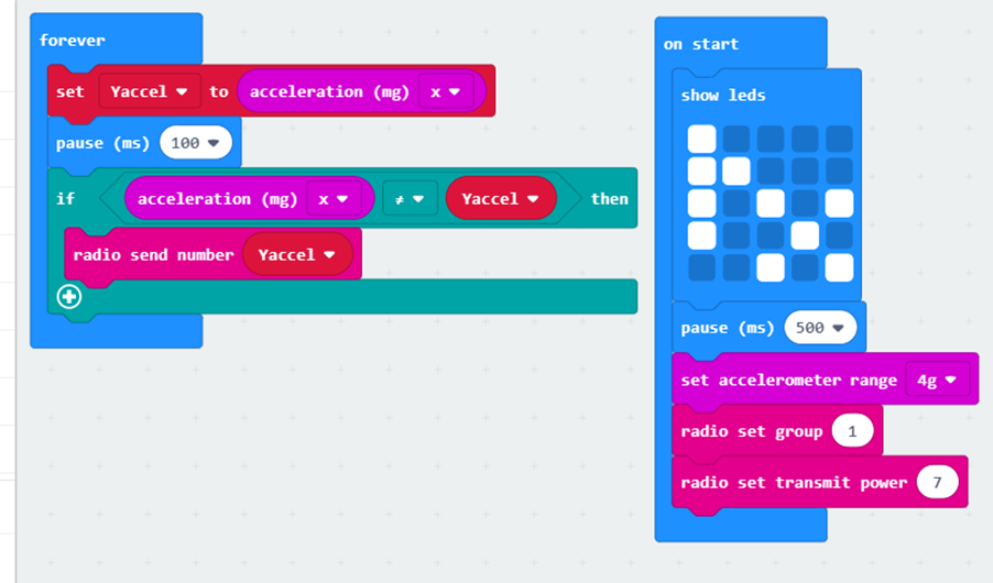
The second Microbit is the receiver, set to receive and then to serially transmit data to a laptop computer, perhaps using a terminal emulator like TeraTerm, from which the data can be sucked into Excel and worked on, as shown below.

Now you are ready to test. The simple example below is for a vertical chute, showing a prompt acceleration at nearly 1g, then decreasing slightly, before hitting the cushion at the bottom which gives a short sharp negative acceleration.

You can then ‘numerically integrate’ the acceleration recorded to get a velocity versus time profile. This can be done very simply in the spreadsheet. Put receive times in column A, accelerations in column B, and by an expression such as C5 = C4 + (B5+$G$2)*(A5-A4). In this, $G$2 contains an estimate for the Microbit’s measured value of g. So each value of speed is calculated from the previous value :
V(i+1) = V(i) + Δt (a(i)-g).
The results on this vertical drop run are shown.
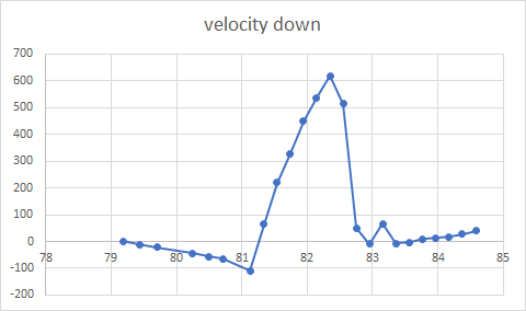
Why does Ginny not simply plummet downwards at constant acceleration of g ? The plastic tube is clearly doing something to slow down that plummeting. There is perhaps an effect due to air being pushed along the tube. But probably the stronger effect due to friction of Ginny on the plastic film.
Other things to try
Although a vertical escape chute is interesting, and simple to engineer and test, it is clearly letting Ginny drop rather more precipitously than would be desirable. There are vertical or near-vertical escape slides. They were used by NASA, for example on the Space Shuttle. You need to increase the friction of the vertical tube for it to work well. How ? Use a higher friction material perhaps, or an inflated outer tube – pushing the inner tube inwards, perhaps ? Or maybe circumferential or spiral strings, or maybe elastic elements ?
But the more common slides are sloping. How can you make a sloping slide ? Simply stretch a flexible U-shape or tube between high and low points the correct distance apart ? Or but maybe use inflatable parts, as used in the slide escape systems of aircraft ? Need to add more friction to the slide / chute ? How can you record the acceleration usefully, and how can you calculate the speed down the chute ?

And Finally…
What about modifying the vertical escape chute further ? What happens when you twist it ? What happens when you taper it ? And for a sloping slide, what about a two stage system, sloping at two different angles, steeper to start, shallower to finish ?
