Here are a selection of things that show you something different and entertaining, and which can be put together and tested out in a matter of minutes.
- Drainpipe trumpets #drainpipetrump
- Oscillating Air Worms #airworms
- Hoverpets #hoverpets
- Boyle’s Law Bangers #boylesbangers
- Whirling Hose Pumps #whirlinghose
- Tissue Trigger Catapults #tissuetrigger
- Ice and Fibre #iceandfibre
- Magic Rim Roller #magicrim
- Waltzing Tube #waltzingtube
…
…
Drainpipe trumpets
“The beat of a different drum” : Title of Jagdish Mehra’s biography of Richard Feynmann, who won a Nobel Prize in Physics.
A drum is usually used by hitting it with a stick – sometimes padded. Most drums don’t make any particular note, they just make a percussive noise. But some drums, like orchestral kettle drums (timpani) can be tuned, so that they produce a particular note, at least roughly. So it shouldn’t be a complete surprise that you can make a drum which can produce a tone. The key to producing a continuous tone is to provide a continuous source of energy. One way to do this is to use a stream of air, and that is what we use in the Drainpipe Trumpet, which is thus really a very different kind of drum.

What you need
- a large, short piece of pipe, eg. 40-70mm diameter
- a longer piece of small pipe, eg. 10-15mm in diameter
- elastic bands
- latex rubber balloons

What you do
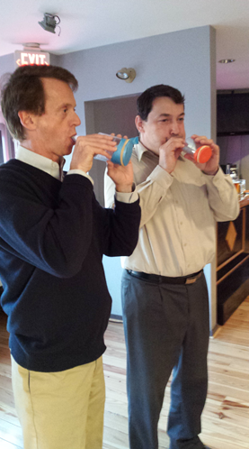
Teamwork is needed to make a Drainpipe Trumpet: Someone needs to hold the drainpipe while another person stretches the balloon over its end and then someone can fasten an elastic band around the pipe. Sometimes it helps to inflate the balloon fully – then deflate it and you will find it is a little bigger and easier to stretch, so that you can fit it to the large short pipe section more easily.
Now just blow down the small pipe, pressing it against the diaphragm as you blow, adjusting how hard you press until you get a note. You just blow – don’t try to use your lips as a source of sound, as they would be in a conventional trumpet.
Try blowing harder/softer, pressing harder/softer. Can you get different notes ? Does it matter where the small pipe touches the membrane ? Try pressing the tube onto different parts of the drumskin when you blow. Can you get higher and lower frequencies – and what positions on the drumskin do you get these frequencies.
The Way Drums Vibrate The ways a drum like an orchestral kettle drum can vibrate are more complicated than you might expect. The normal way that the kettle drum is made to vibrate is that you hit it about 4” from the edge. It then vibrates with a more resonant sound than if you hit it in the middle, for example. Most of the vibration is one in which one side goes up while the other goes down, with a line across the diameter which doesn’t move. This is called the λ11 mode.
There are other modes like the most obvious one, known as λ01 in which the whole skin goes up and down at once with only the edge not moving, and the greatest movement in the middle. If you hit timpani in the middle, they mostly vibrate in this mode, giving a less resonant tone. The diagrams below show some of the modes of vibration. Kettle drums, depending upon how you hit them, will vibrate with several modes simultaneously – which is really complicated !
Drainpipe Duet
And Finally… Can you improve the Drainpipe Trumpet in some way ? You could try different balloons and single and double thickness. Does it make any difference how you stretch the diaphram ? Can you tension the diaphragm by pressing a finger on it and still get a note ? Can you improve the Drainpipe Trumpet in some more fundamental way ? Make it louder, lower, higher ? Sketch your idea until you are happy with it – and then try making it !
…
…
Oscillating Air Worms
Put a long tube of plastic film on the outlet of a hair drier and you have made an oscillator, a system that repeats a movement at regular intervals.
It isn’t the kind of oscillator that can generate a sound anyone can hear, because it isn’t fast enough. To be heard, it would have to oscillate 50 times or more per second, rather than once every couple of seconds or so it might manage. And it isn’t the kind of oscillator that you find in lots of electronic equipment, which may run at 32768 oscillations per second (in your quartz watch or block), all the way up to megaHerz (millions per second) or gigaHerz (billions per second).
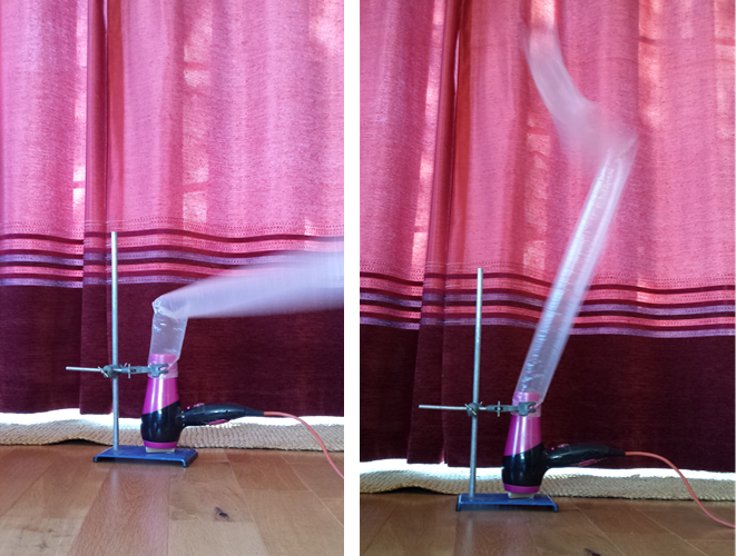
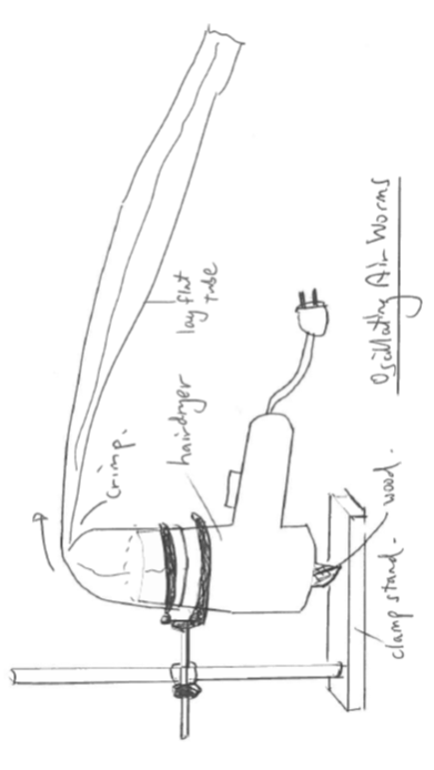
You need to set up a hair drier on a base pointing vertically upwards with the long plastic tube. Once you have set it up, switch on the hair drier on ‘cool’. The tube will start from a lying down position, with the tube having ‘crimped’ near the start where it joins to the hairdryer. When you switch on the hairdrier, the tube will fill up by moving the start of the tube more upright pushing the crimp along, the tube filling up below the crimp and tending to go upright, and dragging the end of the tube upwards too. After a second or two the crimp will reach the far end, and then, suddenly, the air fed in won’t be trapped any more. The air will whoosh out and the tube will collapse towards the floor again. But then the process will start again…
Each time the tube falls, it will tend to fall in a different direction, giving the Air Worm a certain degree of randomness. But it doesn’t much matter which way it falls, it will still rise again.
Hazard WarningTake care with mains powered electrical items like hairdryers. They have the potential for both electric shock and overheating. Always put the hairdryer on ‘cool’ setting. It will still warm up, but nothing like as much as it would if it were on ‘hot’. The fan will pump nearly as hard, but the air comes our only luke-warm. If at any point, the hairdryer becomes blocked off for more than, say, 30 seconds, then switch it off. (It might otherwise overheat, and although it will have a thermal cut-out switch which would stop it from catching fire or anything else serious, the thermal cut-out switch might not be resettable, and other minor damage might be done.)
Why does it oscillate ? The tube, when bent over, forms somewhere near its base, a ‘crimp’, where the cross-section, which becomes round when filled, is flat. As the hairdryer blows, it fills up the tube, forcing it to vertical in the filled part and forces the crimp to travel along. When the crimp reaches the end, the air is released, and the tube collapses sideways. This creates another crimp at the base… and so on ad infinitum.
Try making the tube different lengths. Time how long it takes to cycle from upright to sideways and back to upright again. You will find it is a bit unpredictable, so you might want to measure ten cycles How could you make it faster still ? What happens if you add a tiny weight to the tip ?
How long a tube will still lift ? Can you use a narrower or wider tube ? What difference does the width of the tube make ?
When the tube collapses at the end of the cycle, will it matter which direction it collapses in ? The tube starts off flat, which gives it two creases down its length, which might be expected to change its behavior a little. But does the direction the tube falls relative to the creases make any difference in practice ?
And finally… What could useful thing could you do with the oscillating air worm ? Could it, for example, ventilate a room that was stuffy or keep it cooler, by moving the air around ? Could you use it to test hairdryers and other air fan machines ? Could you maybe spread seed over a field with it by dribbling tiny seeds into the airstream ? Find yourself a large sheet of paper and sketch out a few ideas.
…
…
Hoverpets
Sorry ! Coming soon !
…
…
Boyle’s Law Bangers
Boyle’s Law was first explored in detail by Robert Boyle of Oxford, hence the name. He was interested in flow and pressure and also investigated the circulation of blood. His law says that when you decrease the volume of a fixed piece of gas, then the pressure will go up in the same proportion as the volume goes down. Squeeze gas down in volume by a factor of two, and it will go up in pressure by a factor of two. Squeeze the gas to a tenth, and it will go to ten times the pressure.
When a balloon is popped, a relatively large volume of air, at just a little over atmospheric pressure, is released, providing a sudden sound pressure wave in the air, a ‘bang’. But it is not the only way to create a loud bang, you can use a smaller volume of air at much higher pressure. Here is how to use the high pressure approach to making a loud bang using a bike pump.
You may be surprised to learn that a Boyle’s Law Banger will release quite a lot of energy – something on the order of a a MegaWatt !
asdf
What you need
- Bike pump
- Soda bottle
- Glue, Duck tape
- 40-50mm wide ‘Sellotape’ (must be a thin self-adhesive tape (clear or brown ‘parcel’ type), the thinnest grade
What you do The picture above shows stages in making a Boyle’s Law Banger, from bike pump at bottom to Banger at the top. First saw off the end where you would normally screw in the tyre-filling hose – just taking off the end will generally do. It is worth checking, however, that the plunger inside does go nearly to the end of the tube – otherwise, the pressure build-up might be insufficient. If necessary, saw off a little more.
Now take a soda bottle and cut or saw the end off: you just need 30mm or so of the bottle neck past the screw thread part, maybe a total of 50mm. Glue this onto the end of the bike pump with hot-melt glue, making a really good job of it: you don’t want this to come off. You may need to sandpaper the pump end if it is shiny and slippery, perhaps coating it with cyano glue to improve the grip. Similarly the inside of the soda bottle neck. And for an insurance policy, wrap a couple of turns of duck tape tightly around the outside of the joint. Next you modify the bottle screw-on cap by drilling a large hole through it. This large hole can be a little tricky to make. You can just drill it, perhaps using a spade-bit in a small drill-press (sometimes called a pillar drill), holding the cap in a drill-press vice. Another way to make the hole is to sharpen the edge of a short length of tube, put the cap on a piece of wood in a vice and wind the vice to drive the tube through.
Now you can ‘arm’ your Boyle’s Law Banger by sticking a small square of material over the bottle neck. Start with paper, then work up to stronger materials like Sellotape or other thin plastic tape. You will need to find tape that is just a little wider than the standard 25mm tape – 47mm is one standard bigger size. Then screw the cap with the hole over it. Make sure everything is well ‘snugged down’ and leak tight.
Now prepare to pump the bike pump just once, but pushing as hard as you can. With luck, the volume will go down, the pressure will go up – and up – until the square of tape can take it no longer and… BANG !
Try different materials. Paper is porous, so maybe isn’t the most obvious thing to try. However, it’s not very porous and if you are compressing the air quickly, the air leaking through the pores won’t matter. Greaseproof paper works, and is not as porous. For a bigger bang, however, you will need stronger material. Too strong, of course, and you won’t be able to get to a high enough pressure to burst it. Try the thin film parcel tape – often coloured brown – or wide office tape, the clear ‘Sellotape’ or ‘cellophone’ tape or similar. You probably won’t want to try out the more stretchy materials like kitchen cling-film or PVC electrical insulation tape once you have seen how much even a strong rigid tape like Sellotape bulges out. Too flexible – too low a modulus of elasticity, scientifically speaking – and the material will simply bulge out into a large section of a sphere and won’t burst.
Young’s Modulus of Elasticity and Minimum Crack Size
If you have picked up a container of silicone gap filler – as used around bathrooms – you may have wondered what the phrase ‘low modulus’ or ‘high modulus’ means. When you compress or stretch something, it tends to give a little. Technically we say that you apply a stress, and the material is strained. The stress S is simply the force divided by the area at right angles to the force, so S = Force/Area. The strain e is the change in length ∆L divided by the length L, or e = ∆L/L
The ratio of stress S over strain e is the modulus of elasticity or elastic modulus, or, if it is tension stress over tension strain, the ratio E is called the Young’s Modulus: E = S/e.
Can the tape just crack a little, or have a small hole, and then just leak air out ? You will probably find out that this doesn’t happen: it either stays intact, or it is blown away completely with a bang. Why ? Its all down to exceeding the minimum crack propagation length. Cracks grow when the energy released by more crack is greater than the energy lost by creating the crack. The energy released is Er ~ T L², where T is the surface tension and L is the length of the crack. Whereas the energy needed to create the crack is (say) S per unit length, so Ec = S L. So if Er > Ec, then the crack will extend. So if T L² > S L, i.e. L > S / T then crack will extend, or in other words, Lmin = S / T where Lmin is the minimum crack propagation length.
In everyday life – and in engineering – we often need to know how much force is on something. Now in outer space, in a vacuum environment without any air, the force on the inside a pressurized container, the force on a piston with pressurized gas behind it, is just proportional to how much gas is there in each unit of volume (and how hot the gas is). We can measure that force, divide by the area over which it is measured and we call that the absolute pressure.
But here on the surface of Planet Earth we are living at the bottom of an ‘ocean’ of air. And that ocean of air has its own pressure – atmospheric pressure. Something like a container or a tyre or a piston and cylinder full of gas will have gas pressure on the inside, and atmospheric pressure on the outside. Now how the gas on the inside will push with a force proportional to its absolute pressure and the area. And the atmosphere on the outside will push back with a force proportional to its absolute pressure – atmospheric pressure. The net outward force on the inside of the gas container will be the gas force minus the atmosphere force, which is equal to the inside pressure minus the atmospheric pressure times the area. This quantity – gas pressure minus atmospheric pressure – is a useful thing to know here on the surface of the Earth , and we call it ‘gauge’ pressure, because it what is usually shown on the dial of a pressure gauge, because it is the quantity you mostly want to know about.
We don’t have to try hard to make a gauge that shows gauge pressure: many pressure gauges just show this naturally. A standard round pressure dial gauge or ‘ Bourdon’ gauge, and that laboratory favourite, the U-tube manometer, show gauge pressure anyway. If you block up one end of a U-tube manometer, then you have an absolute pressure manometer, one which can measure absolute gas pressure or atmospheric pressure: this is in fact the old-fashioned mercury tube barometer.
Gauge pressure and Absolute Pressure: In everyday life – and in engineering – we often need to know how much force is on something. Now in outer space, in a vacuum environment without any air, the force on the inside a pressurized container, the force on a piston with pressurized gas behind it, is just proportional to how much gas is there in each unit of volume (and how hot the gas is). We can measure that force, divide by the area over which it is measured and we call that the absolute pressure.
But here on the surface of Planet Earth we are living at the bottom of an ‘ocean’ of air. And that ocean of air has its own pressure – atmospheric pressure. Something like a container or a tyre or a piston and cylinder full of gas will have gas pressure on the inside, and atmospheric pressure on the outside. Now how the gas on the inside will push with a force proportional to its absolute pressure and the area. And the atmosphere on the outside will push back with a force proportional to its absolute pressure – atmospheric pressure. The net outward force on the inside of the gas container will be the gas force minus the atmosphere force, which is equal to the inside pressure minus the atmospheric pressure times the area. This quantity – gas pressure minus atmospheric pressure – is a useful thing to know here on the surface of the Earth , and we call it ‘gauge’ pressure, because it what is usually shown on the dial of a pressure gauge, because it is the quantity you mostly want to know about.
We don’t have to try hard to make a gauge that shows gauge pressure: many pressure gauges just show this naturally. A standard round pressure dial gauge or ‘ Bourdon’ gauge, and that laboratory favourite, the U-tube manometer, show gauge pressure anyway. If you block up one end of a U-tube manometer, then you have an absolute pressure manometer, one which can measure absolute gas pressure or atmospheric pressure: this is in fact the old-fashioned mercury tube barometer.
Boyle’s law works on absolute pressure. If you have gauge pressure in your measurements, then you should subtract atmospheric pressure from them all. The table below shows how the pressure varies with the volume of the air.
| Volume | |||||||||
| 100 | 90 | 80 | 70 | 60 | 50 | 40 | 30 | 20 | 10 |
| 1.00 | 1.11 | 1.25 | 1.43 | 1.67 | 2.00 | 2.50 | 3.33 | 5.00 | 10.00 |
| (absolute) Pressure |
asdf
You can plot a Boyle’s Law curve like this by fitting a bike pump with a pressure gauge and just measuring how far you have pushed the plunger. The gauge be calibrated in gauge pressure, so subtract 1bar from all the pressure readings. You will find it hard to get beyond about 8 bar (7 bar gauge) unless you have been working out in the gym !

What about how much sound the Banger makes ? You will have heard how much louder some materials sound – and how these tend to be the ones which are harder to burst. Why not find a mobile phone and load up a sound meter app, or maybe a proper sound meter and test the loudness ?
You need to set up to record the peak sound intensity. And you will need to set up so that the distance to the Boyle’s Law Banger is the same for each test. As the distance increases, the noise level recorded will go down. In the middle of a field with nothing to reflect the sound except soft grass, the sound will decrease according to an inverse square law. Inside a room, it isn’t so big an effect, because of the echoes from walls, ceiling, a hard floor and other reflecting objects in the room.
Megawatt Output: You can estimate the energy if you know that the energy in a compressed gas is PV and that it will be released in a short time – the time it takes a crack to cross the thin plastic membrane sealing the end. Figure PV out for your pump and you will probably come up with a figure like 10 Joules. Now the time it takes the crack to go across the tape can be debated, but is probably something like the speed of sound in plastic. If we take 2000 ms-1 (most are faster than this) and 20mm crack, then we have time to crack of just 10 microseconds, which means that our 10 Joules will be released at a power of something 10 J / 10^-5 or a MegaWatt !
(BTW: The energy is more accurately PiVi loge(Pi/Pf) where P is pressure, V volume, i initial, f final., so the actual energy might be 2 or 3x more).
Who can make the loudest banger ? Can you test your own and other people’s strength by seeing what is the strongest material that can burst in the Banger ? You could start with something easy like greaseproof paper and then work up to stronger sticky tapes.
And Finally… Can you get a video of the Banger exploding with a high speed camera, one that runs 10x or faster than the standard 24 frames per second ? Can you think of a better design for the Boyle’s Law Banger ? Could you fit the soda bottle onto the end of a bike pump without sawing the end off it ? Could you modify a foot-pump somehow ?
…
…
Whirling Hose Pumps
If you are ever stuck in a sinking boat, but have a length of hose pipe, then the Whirling Hose Pump could save you and your fellow mariners from a one-way trip to Davy Jones’ Locker. Pumping water is important – very important – to humanity. The water we drink is pumped to our houses. Much of the food we eat is grown with water that is pumped from rivers or from wells. And water pumped at high pressure is mostly what stops our towns and cities from destruction by fire.
This importance means that a huge amount of ingenuity is devoted to making simple efficient pumps. But that doesn’t mean that there is no room for new and unusual design. Here we explore how a length of hose whirled around your head can work as a kind of centrifugal pump…
What you need
- bucket of water
- length of PVC common-or-garden hosepipe say ~ 4-6m long
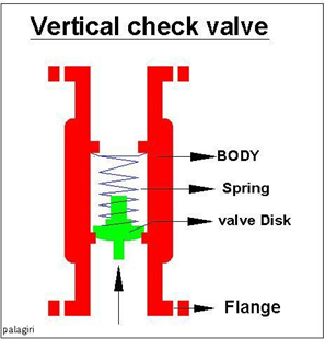
- one-way or ‘check’ valve
- optionally, short length of plastic pipe bigger than hosepipe
What you do: The basic idea of the Whirling Hose Pump is simple: dip one end of the hose in the liquid to be pumped – a large bucket of water, say – and take the other end and whirl it around your head. In practice, however, there some things you need to get right to get it working.
Firstly, you need to fill up the hosepipe with water – what in the world of pumping is called ‘ pump-priming’. Put a crimp in it by bending it over, or get your assistant to. Then use a funnel and a plastic jug to top it right up. Then, keep it upright so that you don’t lose any water from it, get ready to swing it around
Your assistant needs to keep the bottom end in the water at all times: he or she must not let air into the hose. The hose will squirm and try to escape as you whirl it around. The problem of the Whirling Hose Pump is getting it full, and keeping it that way until you have it swinging at full speed around your head. You need to get it up to speed and swinging fast quickly. Maybe your assistant can let the crimp go at the moment that you get speed up.
Conveniently, hose pipes are often provided with a check-valve, a one-way valve, that lets water flow from the tap, but not back into the tap (this is to stop the dirty garden water by some chance from getting back into the house water pipes). This provides a much easier way to get the hose pipe full and keep it full until it is pumping. You can now simply fill up the hose pipe and it will stay full if you keep the tip higher than the bucket and somewhat vertical until you start swinging it.
Some grades of plastic used in hosepipes, although smooth, have a relatively high frictional force, they won’t squirm freely enough. To reduce friction, you may find it helpful to apply a little grease of some kind to the hose, so that it can turn fairly freely in your hands as you whirl around. Even better, you can use a short length of pipe which will slide and rotate freely on the hosepipe, and use this as your handgrip on the hosepipe. Your assistant can do the same.
The pump pressure depends upon the acceleration of the tip of the those – which is proportional the square of the speed of the tip. So increase by a factor of 2 the rotation speed of your hose and you will boost the pressure squirting the water by a factor of 4. With luck, you will be able to empty even a large 10 or 20 litre bucket very quickly. And one of the wonderful things about the Whirling Hose Pump is that the operators get a lot less wet than the spectators !
And Finally… What else could you do with the Whirling Hose Pump ? Could you adapt it to pump water out of wells for growing plants ? Or for draining water out of the bottom (the ‘bilges’) of boats ? How could you get power to the rotating hose and do it automatically ?
And Finally… What else could you do with the Whirling Hose Pump ? Could you adapt it to pump water out of wells for growing plants ?
…
…
Tissue Trigger Catapults
In engineering everyone usually looks at making things stronger. We don’t so often look at ways to make things weaker. When you blow your noise on a tissue, or try to mop up some liquid with a kitchen towel, you will have noticed how the tissue itself, once wet, is much weaker. In fact, it may have almost no strength at all. Papers vary in their ‘wet strength’, but tissue and similar papers have a very low wet strength.
It is this fact that is the key to the Tissue Trigger Catapult. The Catapult can take various forms, but it includes somewhere a piece of tissue which holds the device back. On wetting the tissue, it becomes weak, no longer holds, and the energy stored in the catapult is released.

What you need
- Wood block
- nails
- tape
- ‘Kleenex’ or similar tissue
- 15cm (6“) ruler with hole at one end (drill one if it doesn’t have one)
- matchstick
- elastic band
What you do: The catapult in the sketch is as simple as I could think to make it. The pair of nails can be hammered well into the wood and can be shorter, the one at the back should stick up further for the elastic band to go over. The 15cm/6” ruler is hinged against the two nails at the end and pulled back by the elastic band so that it is trying to lift up and launch itself upwards. The elastic band is held by a matchstick or similar little stick behind the hole in the end of the ruler. But the ruler is held back by the strip of tissue taped on to the wood block.
What you do: Once you have made something that looks like this, and ‘set’ the catapult by taping on the tissue, stand back, and arm yourself with a water pistol. Take aim at the tissue with a squirt of water. TWANG !
With luck, a fraction of a second after the water gets on the tissue the ruler will launch itself across the room. Now test out how narrow you make the tissue. Or how many elastic bands you can put on the ruler. Can you make it bigger – does it work with a 12″ ruler ?
And Finally… How could you improve the Tissue Trigger Catapult ? Could you make it fire a projectile other than the ruler itself ? Could you make a gravity-activated ‘siege engine’ like a trebuchet ? How much energy could you store, and still hold it from release by a single strip of tissue a few cm wide ? What use could be made of a device based on the Tissue Trigger ? Back up for your alarm clock ?
…
…
Ice and Fibre
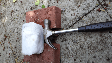
What is the world’s only bullet-proof inflatable cushion ? Now come on, you must be thinking, surely anything inflatable can’t possibly be bulletproof. Most of an inflatable device is air, and that definitely is not bulletproof. Well, we will be cheating a little – we will be using water instead of air. But even that it is not enough. Water isn’t bulletproof either, unless you have a swimming pool of it. Here we make something that is 95% pure water but will resist powerful blows from a hammer.
Ice is weak, very weak. You may think it quite tough as you pirouette across it at an ice-skating rink. But standing on it with a cement floor just underneath it is hardly a stringent test of its strength. Take a slab of ice and hit it even quite gently, and you will find that it disintegrates pretty easily. Its so weak that even the least imaginable tap from a hammer will crack in two a kilogram block, even as above with the block spanning two supports.
What you need
- freezer
- oblong (rectangular) margarine or similar plastic containers, eg. 1kg size
- water
- polyester cushion stuffing
- hammer
- goggles
- bricks or wood blocks to support test block
What you do: You need to make up a block of ice, and an identical block with fibre using the same containers as moulds. Include just 5% by weight of fibres in the icefibre block. For example, try a handful of the fibre used to pad cushions. In the icefibre block you have something of a completely different character, a material with definite engineering potential. If you have done it right, the new icefibre block will be almost impregnable. But first done your goggles and prove to yourself with a rather gentle blow with the hammer how weak the pure ice block is. And now try the icefibre composite out versus a hammer attack. You may find that you need to hammer at several times, using more and more force, and even then not break it cleanly. Even supporting at the ends with bricks won’t render your icefibre much more breakable.
Pykrete and the Iceberg Ships There was a plan in the desperate war-torn days of 1943 to produce ships made of reinforced ice, so large that even the largest bomber aircraft of the day could take off from them. The reinforced ice was named Pykrete after its inventor, Geoffrey Pyke. They would have been produced in northern latitudes using the naturally low temperatures there, pumping water wood-chips into vast moulds of some kind during the freezing process. The Iceberg Ships never went to war, but the idea was tested in the Great Lakes, and the science was sound.
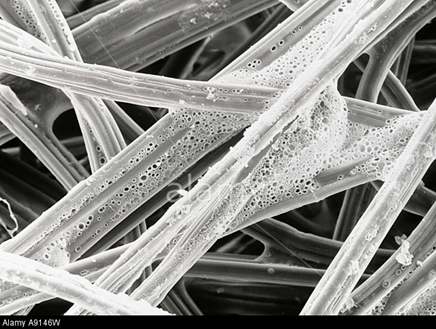
The Science of Fibre Reinforcement: Fibre reinforced composites can be tough. This has been known since the earliest civilization, where straw was used to reinforce mud-brick. This combination is so good in hot dry places, that mud-brick structures have survived 5000 years !
First some terms: a composite material is made from fibres and matrix (resin – ice in our case here). The fibres typically have a high Young’s Modulus E of elasticity: in other words, they don’t stretch much you strain them. The matrix typically has a lower Young’s Modulus.
E = Stress / Strain
where Stress = force/area and Strain = elongation / original length.
Fibres add tensile strength to a composite. In our case, ice is typically measured to have strength of order 1 MPa, or 10kg/cm2. But the polyester fibres will be 200MPa or more – hundreds of times stronger. The fibres just need tensile strength. They can be brittle – amazingly, glass, one of the most notoriously brittle materials, is one of the most successful reinforcing fibres. The essence of fibre reinforcement is that it stops crack propagation: a crack starting in one fibre won’t go through to another fibre easily. Why ? Because at the interface between the matrix and the fibre, the lower modulus means that the matrix will simply stretch a little when the crack reaches it. The crack only cuts through a single fibre.
Composites are also ‘tough’. Toughness has a technical meaning in materials science: it refers to the amount of energy that a material can absorb before it breaks, per unit volume. A sheet of ice – or (non-heat-treated) glass – is one of least tough materials: touch either with a hammer and they shatter, cracks running all over them in milliseconds. But the icefibre of this projects is spectacularly tougher than the virgin ice !
More to Try : Weigh out the amount of fibre that you use, and try different amounts. Try different fibres. Maybe you can also test different temperatures of ice. There have been experiments with civil engineering with ice and fibre – often wood-pulp reinforced ‘Pykrete’ (see below). Huge Domes , docking quays have been tested. The US TV crew of Mythbusters even tried a fibre-reinforced ice boat ! Can you measure the toughness (energy/unit volume) in Joules per m3 required to break your icefibre ?
References: Michael F Ashby & David R H Jones, Engineering Materials 2, Pergamon Press, (3 vols 1992) (eg. Chapter 25); Mark Miodownik, Stuff Matters, Penguin (2013), ; B.Harris, Developments in GRP Technology, Applied Science Publishers (1983)
…
…
Magic Rim Roller
Amaze all your friends with your abilities to balance a roller on top of a bike wheel rim. And then hand it over to them and show them how hard it is to do ! Fear not, this does not require hours or weeks of learning hands-on skills – there’s a trick – and some science – involved.
…
…
Waltzing Tube
Fortuna Rota volvitur; descendo minoratus; alter in altum tollitur.
The Wheel of Fortune turns; I go down; Another is raised up. (Carl Orff, Carmina Burana)
Amaze all your friends and… And maybe win some money off them – if they dare to bet against you magical power to determine whether a spinning tube shows a Nought or a Cross. All about a simple Victorian toy which spins on two axes simultaneously – and the curious theory of how it works. It still has the same power to fascinate as it did 150 years ago ! Here’s a video clip showing one way the tube can spin anti-clockwise: https://www.you.com/watch?v=Tap2cDg36rE
And here’s another showing another way the same tube can spin also anti-clockwise: https://youtu.be/BVPFkdhyMik
Although the waltzing tube is a device that calls to mind a “wheel of fortune,” it is not random or probabilistic but rather perfectly deterministic. It is ludicrously simple, so simple, in fact, that no one should read past this chapter without writing some symbols on a piece of tubing and spinning it around. Once you know its secret, perhaps you can convince someone else that it is a probabilistic device like a wheel of fortune and then win some money from them!
What You Need: A piece of rigid cylindrical tubing whose diameter is an exact multiple of its length (e.g., a length of 25-mm drain pipe or a piece of strong small-diameter cardboard tubing). That’s it !
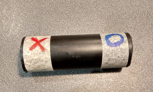
What You Do: Cut your tube; a piece with a length that is three times the diameter is a good place to start. (You can either measure the diameter directly, or you can measure the circumference and then calculate the diameter, recalling that the circumference of a circle is π times its diameter.) Make sure that the tube is fairly close to an ideal cylinder; that is, make sure it has no burrs and so on, and cut the ends square. Using a permanent marker, mark a bold symbol on the outside of each end of the tube, for example, an ‘X’ on one end and an ‘O’ on the other.
Now spin the tube. By placing a finger on one end of the tube and pressing down while pulling backwards sharply, you should be able to cause the tube to rotate both around the horizontal axis running through the empty middle of the tube and simultaneously around a vertical axis. After a second or two, the tube will begin to spin regularly, and then, magically, one of the marks will reveal itself in almost perfect clarity as it flashes briefly into view, momentarily stationary, and the other symbol will remain invisible, blurred by the motion of the tube. The number of times that the visible symbol appears depends on the geometry of the tube.
What does a symbol written inside the tube do? Try writing a symbol inside an otherwise blank tube. Now spin the tube and view it from the side so that you can see the symbol as the tube end passes you. Is the inside symbol also visible one, two, or more times per revolution? With an opaque tube, you won’t be able to see more than one. Maybe a tube made of clear plastic would allow you to see more.
Now try the tube in ‘random’ mode: just spin the tube with finger and thumb around the middle. Try it a few times. What do you find ?
How It Works: The key to understanding this trick is to realise that once the tube is rotating in a stable fashion, it is actually rolling around in a circle rather than simply spinning about a point underneath in the center. Furthermore, the rolling is taking place at an end—the end opposite to the end that you flicked. The image on the rolling end is no more visible than a patch of paint on the peripheral tread of a rolling tire. However, the opposite end of the tube is actually rotating backwards relative to the direction of axis motion at exactly the same speed, so the symbol is momentarily stationary relative to a stationary observer. The symbol actually follows a nonretrograde cycloid path. From the observer’s reference frame, the symbol appears to be sloping to the left about two-thirds of a tube diameter from the ground, rising up and flattening out, and then beginning to slope rightwards and descending—all in fraction of a second. The image will appear in this way twice per tube revolution if the diameter is twice the length, three times if the diameter is three times the length, and so on.
The symbol written on the inside of the tube is simpler to explain. The surface of any rolling wheel is momentarily stationary as the wheel rolls along. If it were not, then the wheel would, logically, be skidding, and most wheels don’t skid most of the time. The view inside the tube is something like the view you would get if you rolled a wheel with marked tread over a glass table and observed it from underneath the table.
The Waltzing Tube has been around for years, certainly since Victorian times. Maybe kids in the Egypt of the Pharoahs, thousands of years ago, played with papyrus waltzing tubes at the feet of the newly built pyramids !
The Waltzing Tube Way to Wealth ? Well, maybe: Now hide your copy of Ink Sandwiches and approach an unsuspecting dupe. Demonstrate the waltzing tube as follows: using one finger from each hand at each end of the tube, pretend to flick the tube at both ends but ensure that in fact only one end is propelled. Explain how the tube shows either one symbol or the other, just as a coin can land on either of its two sides. Let your unwitting volunteer have a go themselves, spinning it with thumb and finger from the middle. Explain that the probability of either of the symbols appearing is not in fact exactly fifty-fifty. Carefully build up seemingly random sequences in which one symbol or the other wins out over a few throws. Now offer to take bets. Lose a few small wagers, but make sure that you clean up on most of the big ones. Finally lose a biggish one and bow out while you are still comfortably ahead. Don’t start laughing all the way to the bank until you are out of earshot of your victim !
The Science and the Math: If the length of the waltzing tube is an exact multiple of the diameter, then the image that appears on the flicked end will be in the same place with each revolution of the tube—stationary. If you don’t have an exact multiple, the image will appear to rotate.
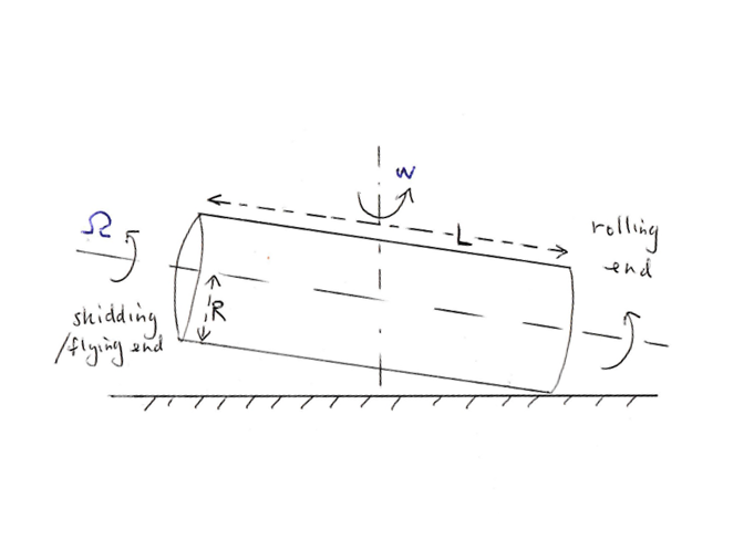
Suppose for example that a tube of length L and diameter 2 R is rotating with angular speed w around a horizontal axis and with angular speed w around a vertical axis. If the tube is rolling on the surface at one end, then the connection between the two angular speeds is given by
w L = Ω R
The bottom of the rolling end of the tube has zero speed. At angular speed w, the top of the tube at the rolling end has a speed given by
(w L + Ω R) = 2 w L
Once the tube is waltzing, one image will appear to blurred by twice the apparent speed of the tube end, while the other will appear to be stationary. The bottom of the skidding end of the tube has speed 2 w L, and the top has zero speed.
For every turn of the tube, the rotating tube end will travel 2 π L. The rolling end of the tube will travel that same distance and, in the process of rotating around, will show the symbol N times, where
N = 2 π L / 2 π R = L / R
So you don’t need to know the value of p. You just need to cut the tubing to a length equal to N times its diameter. If the tube circumference is a half-integer multiple of the length, then two sets of alternately flashing images will appear. If N equals 3.5, then you will see 7 reappearances of the symbol in two circuits of the tube.
Rolling and rotating of the Waltzing Tube: The tube has to be set into rotation about the hollow center and about the vertical axis by the finger’s sliding and pulling backwards. If this is perfectly done, the tube will immediately commence waltzing correctly. However, the launch speed is always at least slightly wrong, which means that for the first few seconds, the tube is skidding at both ends. However, the end that is nearly rolling is slowed or speeded until it actually is rolling, while the other end rotates freely as described, and waltzing begins.
The tube waltzes at a very slight angle to the horizontal: the freely rotating end of the tube has to be clear of the surface. Why does the tube not lie down flat and refuse to waltz ? The tube does indeed stop waltzing once it is going slow enough— it just goes rolling off in a straight line. At higher speeds, perhaps gyroscopic forces help. Or are aerodynamic forces responsible? The tube is light in weight, and may show the ‘Magnus Effect’. Heinrich G. Magnus showed that a long cylinder rotating with a flow past it will tend to lift like a wing. The Magnus force, F, is proportional to the flow speed, u, the fluid density, ρ, the cylinder’s circumference (2 R), and the velocity, V, of a point on its surface:
F = ρ u 2 π R V
With the skidding end of the waltzing cylinder rotating underneath against the direction of motion of the cylinder, there will be a lifting force. However, because our cylinder is very close to a stationary surface, the numerical value given by the equation will be wrong. The effect of the stationary surface is often referred to as the “ground effect,” and it usually results in much larger lift values for the airfoil, a rotating cylinder in this case.
And Finally . . . Quickstepping and Foxtrotting Tubes: What happens if one end of the tube has a different diameter than the other—that is, if the tube is conical—or if it has a ridge at one end? Can you make a tube that flashes up three symbols when spun one way and four symbols in the other? Is a tube better than a solid cylinder? Does the lower moment of inertia of the solid cylinder, which means that it has a lower resistance to changes of rotation speed, put it at a disadvantage relative to the tube? Or do the heavier weight and the limited lift force, whether aerodynamic or gyroscopic, militate against a solid cylinder? Can you fit illuminated symbols inside a waltzing tube?
References: Neil A. Downie, Neil A. “Waltzing Tube”, P.171-175 in Ink Sandwiches, Electric Worms; Karl C. Mamola “A Rotational Dynamics Demonstration.” The Physics Teacher 32 (1994): 216–219.
