Stacks of science with the gadgets that are lying around your house !
- Hacking Electronic Calculators #calculatorhack
- Microwave Steam Balloons #microwavesteam
- Hair drier science 1: Bernoulli Air Bearings #bernoullibearing
- Hair drier science 2: Hover Train #hovertrain
- Hair drier science 3: Air Juggling #airjuggling
…
…
Hacking Electronic Calculators

The humble electronic calculator, when it came, was a giant leap forward. Before that there were only sluggish mechanical calculators, involving lots of winding handles and setting numbers onto dials. Suddenly you could get answers back in the blink of an eye. You could even get something never offered on a mechanical calculator, like a square root key.*
*Square roots: Curiously, the algorithm used to calculate square roots is an iterative calculation first seen in ancient Sumeria (north of present day Iraq) 5000 years ago. The algorithm, first written in cuneiform script, for the square root of number S, is:
Ni+1 = 0.5 x (N i + S / N i)
where Ni is an earlier ‘guess’, starting with N 1, and N i+1 is the next best guess at the answer. Here is a typical calculation for the square root of 7:
| 7 | |
| iteration | sqrt(c1) |
| 0 | 3 |
| 1 | 2.666667 |
| 2 | 2.645833 |
| 3 | 2.645751 |
| 4 | 2.645751 |
These days a calculator costs just a dollar or so. Here we see how you can hack / re-purpose the simple electronic calculator to do other jobs – as a counter, as a counter, very useful as part of another project like a scientific clock of some kind. It is what might be dubbed an ‘intelligent’ counter, one that can count in increments of 1, or 2, of 26, or even 23.14567 if you want. And how to make an invisible calculator, that you can see but no one else can.
Calculators as Intelligent Counters
The principle used in the Intelligent Counter is one that works on most simple calculators, and one that you have probably tried out yourself if you have played around a bit. Enter ‘1’ into the calculator, then ‘+’, then ‘1’, then press ‘=’. You get 2 coming back right ? What happens when you press ‘=’ again ? Most people know that on most calculators, you get 3, then if you press ‘=’ again 4, then ‘=’ again 5, then 6 and so on.
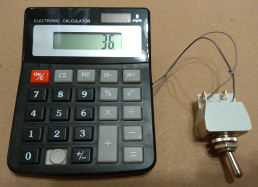
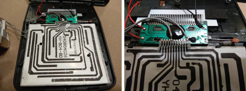
The wires should be taken to the wires on the calculator circuit board that the ‘=’ key of the calculator goes to. Every time the two wires are touched together, or a switch between them is switched on, the display will increment. The wires can go via a 10k resistor, which may help to protect the calculator from a stray voltage doing it some damage. A resistor will also help if you are wiring the ‘=’ key to another piece of electronics. A relay can be used to operate counting. Without the mechanical clunking of a relay, you can use a transistor too. A transistor with input on base, emitter to ground, and the wires from the calculator between collector and, say 1.5V or 3V can also be used to make a higher speed calculator. Try reversing the ‘=’ connections if it doesn’t seem to work. You can check what voltage is between the wires as the calculator circuit board poles the keyboard. (A calculator circuit addresses or ‘poles’ the typical 20 or 40 keys on the keyboard via an X-Y grid, so it doesn’t need as much wiring.) Be aware, however, that most calculators won’t count more than a few 10s or so pulses per second.
Interestingly, you don’t have to count in ones. If you enter a number (A) into a calculator, then ‘+’,, then another number (B), then ‘=’, the machine will come up with the answer A+B. But if you press ‘=’ again, you get A+B+B or A+2B. And if you press ‘=’ yet again, you get A+3B, and so on. This is really useful, for example, if you are trying to make a clock or timer or stopwatch of some kind, and you can’t quite make it count in seconds (or minutes, or hours etc. ). Even if your home-made clock can count in seconds, you might want the display in minutes. So with a seconds clock, simply count in units of 1/60 or 0.01677777 and your display will be in minutes.
Of course, you don’t just have to wire up the ‘=’ key. You could wire up other keys.
Invisible Calculator
The principle here is simple but subtle, simple but quite tricky to explain ! what you do is simple:
- unscrew the body of the calculator
- remove the display, without pulling off any of the wires, if you can, or maybe unplug the display from its socket
- with the tip of a sharp knife (penknife / box-cutter / Stanley knife), pull off the plastic film which is stuck very hard on the front of the glass of the display
- now put it all back together
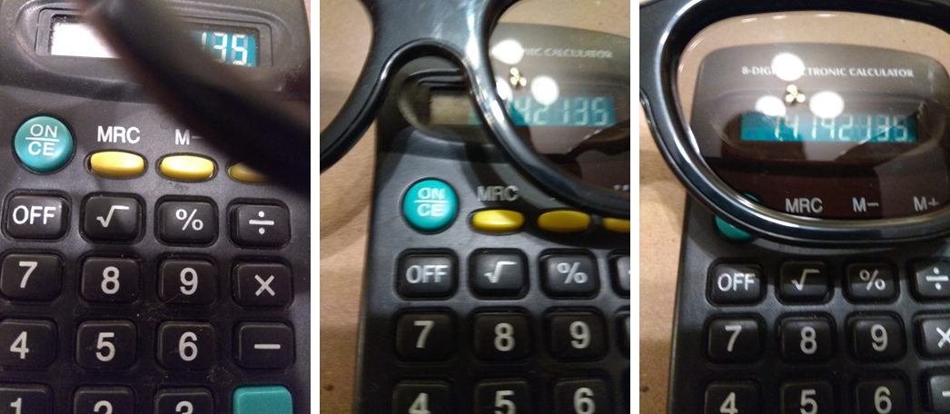
- now you have an invisible calculator – you can do what you like press any buttons, and no one can see anything happening
- put on a pair of cinema 3D spectacles, or fisherman’s glasses – both these sorts of eye-wear have a (different) sort of polarization
- you will now see what the calculator is doing
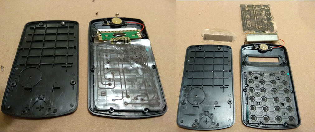
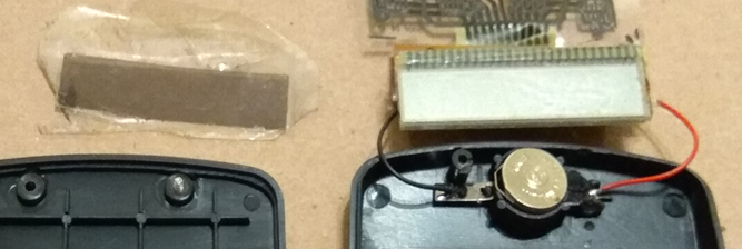
Polariser film (back left) from front of the display (right)
And finally…
What else could you use a calculator for ? They can be made into binary digital transmitters and receivers – ‘Calculator Communicators’ if you like – how to do this as a demonstration of communication principles is in my book, Exploding Disk Cannons. Calculators contain an electronic oscillator of something like audio frequency which can easily be found and which could maybe be useful for something. And maybe you could hack into other keys to do something useful. Could you rewire this, perhaps via an intermediate circuit, back into the ‘=’ key and make a complete clock ? But perhaps a separate – and accurate – oscillator is more useful, like that in a digital watch. Could you take an output from the calculator somehow ?
…
…
Microwave Steam Balloons
This is a simple cheap-as-chips (or french fries if you prefer) demonstration of the properties of solids, liquids and gases. A balloon and an ice cube is all that is needed.
A tenuous, invisible, almost intangible substance. A clear but dense material that flows. And a translucent and somewhat fragile waxy solid. It is difficult to realize sometimes that these are all forms of one material – water. So varied are the forms of water that a famous Victorian Scientist, who studied water in clouds, rivers and glaciers wrote an entire book called ‘The Forms of Water’. Here is how you can demonstrate water in solid, liquid and gaseous form with the aid of a microwave oven and one or two balloons.
You will need
- Balloons – preferably light coloured or translucent ones – the clearer the better.
- Microwave oven – standard kitchen model
- Syringe, eg. 20ml size, is helpful
- Oven gloves
- Safety specs
What you do
Hazard warning: wear safety specs – and give specs to those very close – just in case the balloon bursts. It is most likely to burst in the microwave, but if it is accidentally burst by a sharp point or even a sharp edge on a broken fingernail you won’t want a droplet of hot water in your eye. The water won’t be as hot as boiling – it will cool a lot by evaporation as it flies through the air – but it will unpleasant. Also, use oven gloves to handle the balloon.
You can simply put 15ml or so of water in a balloon, tie it off, and then microwave it. You can just pour the water in, or, to get a more accurate filling amount, use a plastic syringe. You should find that the 15ml of water swells the balloon to almost its full extent. As soon as you take it out of the microwave, it will begin to shrink almost immediately.
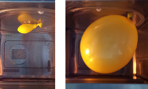
Before (ice, a little water & air) After (steam)
Double Steam Balloon A slightly more sophisticated version of the demonstration is to employ an outer, slightly inflated balloon, outside the water balloon.
Ice Steam Balloon To show all three states of the H2O molecule, put an ice cube inside the balloon. One of way of getting ice in the inner balloon is to put water in, then freeze it.
And finally…
What would happen to the balloon if it were very fully inflated with steam ? Would it fly ? Or would it sink ? The things to think about are the density of steam relative to air, and the effect of temperature. Air, after all, if heated, will be less dense than cold air, which is why hot-air balloons will float up in the air – the air inside them is strongly heated by the huge burner beneath.
…
…
Hair drier science 1: Bernoulli Air Bearings
The Bernoulli family discovered quite a few things that moved the world of mathematics and physics on. Daniel Bernoulli, famously, described how pressures go in flowing fluids – gases like air or liquids like water – behave.
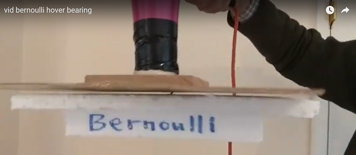
Take a look at The magic of Bernoulli Effect in this video clip: https://www.youtube.com/watch?v=t98ZFbS3KcA
How on earth can the hair drier, blowing down, apparently blowing the block of foam downwards – its weight pushing it down anyway – actually have the curious effect of ‘sucking’ and pulling it up ?
What you need
- hair drier, which must have a ‘cool’ setting – when it runs at pretty much full speed but with very little heat – all the larger hair driers have this feature
- short piece of plastic pipe / tube eg. 100mm long to fit on the air outlet end of the end drier
- piece of plywood, eg. 4-8mm in thickness, eg. 200mm square or circle, to match the foam block
- largish block of polystyrene foam, eg. 200mm square or circle and 30mm thick
- nail / pin
- bit of wood, tape etc
What you do
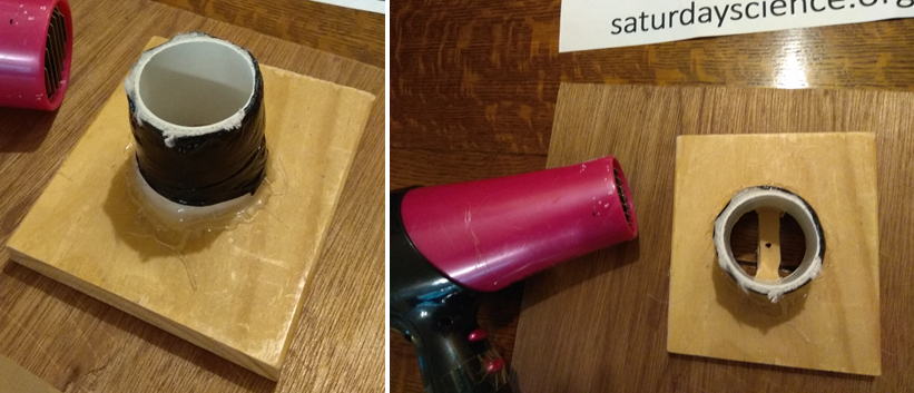
The Bernoulli Air Bearing needs a teeny weeny bit of making, but its good when you have it. First the piece of plywood then needs gluing onto the end of the short length of tube, so that nothing projects beyond the plywood sheet. Then fit the plywood/tube assembly firmly to a hair drier, using duck tape or similar, so that the blast of air from a hair drier can impinge on the block of foam. The tube should have, in addition, across its mouth, a piece of wood 6mm or so in width x 10mm, with a hole in it, maybe 2 or 3mm in diameter, again, nothing projecting beyond the plane of the plywood.
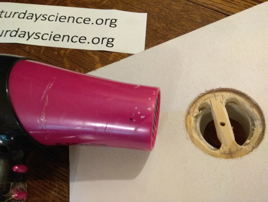
The pin or nail is just pushed through or otherwise fitted in the middle of the polystyrene rotor, sticking out a couple of cm, so that it can loosely fit into the hole in the wood across the pipe: this will stop the rotor sliding off sideways and escaping when you try the experiment.
Warning: Don’t try the following with the drier set to hot, and don’t try it with a drier that doesn’t have a ‘cool’ setting. Without ‘cool’ capability, the experiment won’t work, and you have the risk of overheating the hairdrier. (If the hair drier does overheat, it shouldn’t be a problem. Unplug it and allow it to cool for 5 minutes. You should find that the built-in safety cut-out will allow it to work once more).
Now aim the hair drier downwards, and pick up the block of polystyrene. Hold it so that the pin engages the hole in the air outlet pipe. Set the hair drier going on full power ‘cool’ setting and Bingo ! You should find that the rotor will NOT get blown downwards but instead will suck towards the hair drier and then ‘hover’, just a millimeter below the hair drier and will turn freely in a horizontal plane. Weird !
The hair drier sort of sucks the rotor up if it is too low, and blows it away if it is too high. How does it do that ? Try seeing what happens without the pin. Try aiming the hair drier upwards: does it still hover / suck ?
What is happening: the Science and the Maths
Bernoulli says that in a flowing stream of fluid
P + ½ ρ v² = constant
When the flow comes from the large cross-section of the hair drier and its pipe extension to the narrow disk of space between the plywood and the polystyrene block it has to speed up, because the cross-section of flow has decreased enormously. And when v, the speed increases, Mr. Bernoulli tells you that the P must go down. This may seem counter-intuitive, but Bernoulli often does. The fluid density is ρ, BTW. Although the decrease in pressure is not huge, it acts over a large area, and hence is enough to support the block of polystyrene. Lets estimate the magnitude of the pressures and forces involved…
The Bernoulli equation explains how a ‘venturi’ works. A venturi, named after Italian scientist Giovanni Venturi, is simply a constriction in a pipe with a side-arm pipe attached along the constriction. When fluid goes down the pipe, a low pressure is created, which will suck fluid into the pipe. This the basis of all sorts of useful gadgets from paint spraying guns to petrol engine carburetters and vacuum pumps.
And Finally… More Bernoulli Weirdness
Something you could try as a party trick: a miniature Bernoulli Bearing: You can do something similar by blowing down a cotton reel at a disk made of reasonably thick paper, something up to the size of a CD or so, with a pin in the middle. People can make these and just blow to get the Hover Bearing effect.
…
…
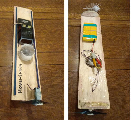
Hair drier science 2: the Hover Train
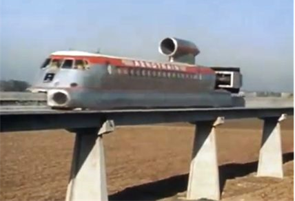
Hover trains were once the fastest trains on Planet Earth.
Mein Luftkissenfahrzeug ist voll mit Aalen
(My hovercraft is full of eels) comedy involving considerable ‘lost in translation’, sketch by Monty Python
The only hovertrain I have seen working myself was the low speed hovertrain shuttle in huge hospital of the Duke University Medical Centre in North Carolina, USA, closed a few years ago (I was supplying equipment for testing the anaesthetic gas Xenon on rats !) I visited the Aerotrain track in France, but there was no sign of the magnificent 270 mph trains – they last ran in the 1970s, although a couple of the prototypes still exist.
Here we look at how you can use hair drier fans and gutter channel to create your own garden hover train. It is a surprise to most people that the vast majority of hair driers don’t have mains (high voltage – 110 or 240 V) AC fans to drive them. They actually use a low voltage DC electric motor. To do this, the hair drier must convert AC to DC and reduce the voltage. The AC to DC conversion is supplied by a four-diode ‘bridge’ rectifier circuit. But how to down convert the voltage ? A transformer ? That is the most obvious way to do it. Transformers are used all over the place, and conveniently and efficiently convert high AC voltages into low AC voltages or vice versa. But there is another surprise: this isn’t how it’s done in a hair drier. Instead, the current to the motor is taken via one of the 2 or 3 wire coils in the hair drier heater section. The coil and the motor act as a potential divider, reducing the voltage from 240 or 110 to 6 or 12. This means that there is a ready source of a powerful low voltage fan lying around in every household, just itching to be converted into a HoverTrain ! Here is a short video clip of one of the many HoverTrain vehicles that have been tried using hair drier fans. https://youtu.be/BEyO3TBTrNk
What you need
- hair drier
- electric motor (same voltage as hair drier motor-fan unit, likely to be around 12V)
- fine pitch propeller, eg. 5″x 3″ 6″x3″ (diameter x pitch)
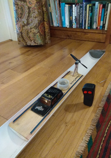
- half-round gutter (but other gutter or other plastic or metal U-shaped sections may also work nicely)
- sponge to make track end buffers
- wood, balsa wood, glue
- wires, switch, battery box / pack (ideally rechargeable) to match motor and hair drier fan
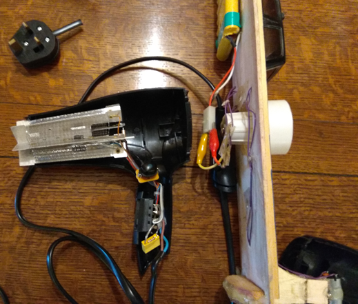
What you do
First test that the motor works and then dismantle your hairdrier. Start by removing the mains fuse and removing the mains plug. Now unscrew the body and extract the motor-fan unit. You now need to do some detective work to figure out what voltage to use for it. It may be marked in tiny lettering with a recommended voltage. If not, try different voltages, starting with 6V or so, and working up until a good little blast of air is obtained without any apparent overheating. They are often around 12V. You then need to get hold of a similar voltage motor to turn the propeller. Small motors are made for model car tracks which may be suitable. The propeller should be a fine pitch (low value) eg. 3″. (Pitch is the distance a propeller would travel if you imagine it screwing its way through very soft butter). These are often sold as spares for drones.
The Science and the Math
At least at lower speeds, the Hover Train may well accelerate as if driven by a constant force, thus following Newton’s Second Law:
F = m a
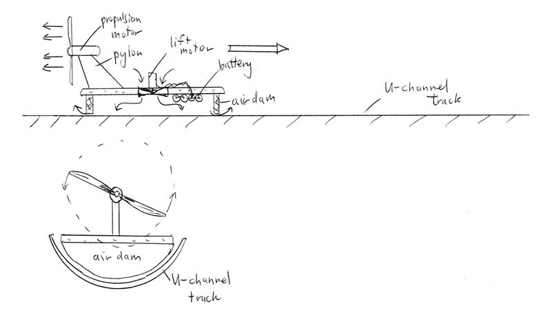
With accelerating force from the propeller F constant, and m constant, the acceleration will be constant too. Of course, at higher speed, various factors, such as air drag and the maximum propeller motor rotation speed, will affect the acceleration increasingly until a maximum ‘terminal velocity’ is reached after a long length of track. The lift force L needed to make the Hover Train actually hover is simply given by multiplying by the fan pressure P the area projected onto a horizontal plane, A, of the Hovertrain sides and air dams:
L = P A
The Train won’t be entirely frictionless, of course, even at low speed, but it should be pretty close. More of an issue, perhaps, is that at very low speed, when hovering, the Hover Train may creep forwards or backwards as a small leak from the ‘air cushion’ underneath it provide a tiny propulsive force.
And Finally…
Try measuring when the Hover Train gets to various point along the track. Does it agree with the expectations of constant acceleration above ? Try increasing its mass by adding masses, perhaps blobs of clay, weighing the complete vehicle. How long can you make the track ? How fast would the Hover Train go if it had enough track ? Can you show that it is no longer accelerating constantly but approaching terminal velocity ? You could try making Hover Trucks: like the powered car, but with only a lift an: no propeller. Because of their low friction once hovering, the powered car should pull quite a number of these, at least on a flat track, although acceleration will be greatly reduced.
References
A much fuller write-up of garden hovertrain projects is in Neil A Downie, The Ultimate Book of Saturday Science, Princeton (2012)
…
…
Hair drier science 2: Air Juggling
“Blow, winds, and crack your cheeks! Rage! Blow! You cataracts and hurricanoes”, William Shakespeare in King Lear
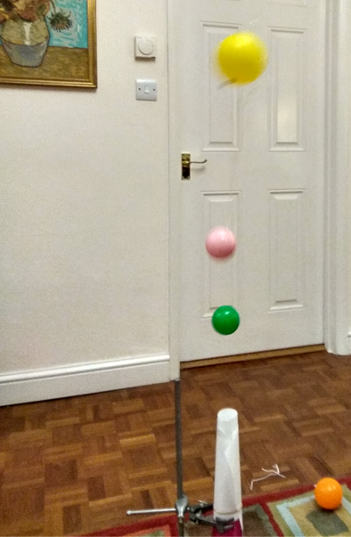
Most people can suspend a small, lightweight ball like a ping pong ball using a hair drier. But suspending two balls, or three, or four, or even FIVE BALLS in the air – that surely requires something out of the ordinary. Just take a look at this video clip… https://youtu.be/kYR4jUcXBLY
That a ball can be supported by a stream of air issuing from a nozzle may at first seem unsurprising. It seems simple: the force of the air blasting on the ball is bound to push it upward. On reflection, however, you will begin to see that it is actually rather surprising.
The ball seems streamlined, so surely flow around the ball should re-form smoothly on the other side of the ball, so viscous drag force supporting the ball. However, air is low in viscosity, and thus this force is so small that unless the ball were made of something little more substantial than spider’s web, one of King Lear’s “raging hurricanoes” would be needed to support even a ping-pong ball !
There is another mystery: why does the ball hover in the middle of the airstream, showing remarkable stability ? If you had not seen it, you might expect the system to be just as unstable as a pencil balanced on its point. If the ball moves off to one side, say the left, slightly, the force from the air impinging from below would no longer below the centre of mass, so surely it should go propelled off sideways to the left, with the impinging airstream itself deflected off to the right slightly.
So why does the ball stay up? First, it is supported mostly by the drag force produced by the formation of eddies behind it (that is, by pressure drag, as opposed to viscous drag, deriving from the viscosity of the air). The drag force produced is much larger than the viscous force, so the air speed can be reasonably slow.
Second, the ball is stabilized by the eddies and maybe also by the rotation induced when it goes off-center (the Magnus effect). These happy circumstances occur only when quite a few conditions are satisfied, however. The airstream velocity must lie between certain limits; the airstream must be not too wide; and the ball must be roughly spherical. Try hovering a ping-pong ball above a wide nozzle—a leaf blower with a cone to widen the airstream, for example–and you will find trouble. If you glue a paper cone on the back of the ball to make it more streamlined, it won’t even hover above the blast from the most powerful hair dryer. Other shapes such as cubes or cylinders also seem to be useless, and very tiny spheres probably won’t work, because flow around them is not turbulent and the drag force on them may be too tiny to support their weight.
Have I now convinced you that supporting a single ball in an airstream, although possible, is really quite improbable? If so, then you won’t need to be convinced that four or five balls balanced above one another in a jet of air is really quite preposterous. But yet it is possible !
If you just pile a lot of ping-pong balls into the airstream willy-nilly, it won’t work. If you try just two similar balls, you will find that they will hover only briefly one above the other before they collide and one or both is ejected. They are both trying to occupy the same central position and height in the airstream. Only by arranging one to have a higher drag factor or a different weight can you persuade them to hover at different heights and hence to hover without clashing. There are further issues: the airstream must more or less reconstruct its linear form again after impinging on the first ball, in order that there be a good jet to support the second ball. For this, you need to use balls that are fairly smooth and don’t break up the airstream too much. (Although if they did not generate some turbulence, they would not hover in the first place.)
What You Need
Hair dryer with a “cool” setting
(ideally) clamp stand or other means of holding the hair drier blowing vertically upwards
Thin card for cone to concentrate the airstream
Ping-pong balls, other larger balls
Balloons- use the smallest ones you can find – 6″ or less – there are really small ones (4″) sold for use as ‘water bombs’ which are ideal
Cotton thread
What You Do: Make a paper cone for the hair dryer from the card stock. When taped to the dryer, the cone should reduce the diameter of the air outlet by approximately a third or a half and should speed up the air enough to make the ping-pong balls hover. Don’t overdo it and make the exit from the cone too small—the hair dryer will overheat if you do. Fix the hair dryer with its cone in a vertical position with a clamp stand or something. Select ‘cool’ and ‘high’ or similar on the hair drier switches – you don’t need the heat, and the hair drier will be happier to run cooler.
Now you need a selection of ping-pong balls with different drag factors. One way to increase the drag is to carefully attach three or four diametrical rings of cotton thread around a ball. Despite the apparent insignificance of this modification, such a ping-pong ball has enough drag that it will hover 5 or 10 cm or so higher than a plain ball. You can also leave trailing pieces of thread – which has the advantage that you may be able to get a flavour for the turbulence of the air stream.
Another method of making a high-drag ball is to expand it slightly. Warm a ball in boiling or nearly boiling water for a few seconds. Use a pair of spoons, a pair of tongs, or a cage of wires like a wire eggbeater, or some other device so you can suspend the ball in the water without scalding yourself, and without crushing or denting the ball. The ball will expand slightly, although not evenly. The resulting ball will 4–6 mm bigger in its largest diameter and will be shaped like a slightly squashed sphere (an oblate spheroid), like an M&M’s candy. Such a ball will hover a bit higher than a standard ball.
You need to ensure that the drag factor of each ball that you add after the first is sufficiently high so that all the balls are separated by at least a ball diameter. Once you have a selection of appropriately modified balls, you will find it possible to support two or three balls in a column above the air jet.
Place ping-pong balls, virgin or high-drag versions, into the airstream, and measure the height at which they hover. If you mark stripes or sectors on the balls, you will be able to see whether, and around what axis, they rotate. The higher-drag balls will hover higher: they have a greater force on them, so they can fly higher in the airstream, where the stream has widened and slowed slightly relative to the speed just past the nozzle. To extend the principle further, you need much lighter, larger (higher-drag) balls. I used balloons, but I inflated them only very slightly. Once you have inflated them to 8–15 cm in diameter, tie the neck off close to the balloon’s surface. Then trim off the excess neck as close as you can, and maybe use a small piece of tape to hold the remainder of the knotted neck flush with the surface. Ball pond balls are another possibility. Armed with these additional balls, you should be able to balance at three, four or even five balls in the air jet.
The Science and the Math: When the ping-pong balls are hovering over the airstream, their weight is exactly balanced by the aerodynamic drag force of the air flowing past in the upward direction. In dealing with fluid flows, we should always check the Reynolds number to determine whether the viscous forces or inertial forces will dominate. If the inertial forces are large, the Reynolds number will be large, and the flow will be turbulent; whereas at Reynolds numbers of less than a few hundred, flow will likely be smoothly laminar.
If we use the 18-mm radius of a ping-pong ball for L and a characteristic value of 2 m/s for the airstream speed, the equation for the Reynolds number,
RN = ρ V L /µ,
gives a value of about 2,600, which indicates that the inertial forces are large and the flow is turbulent. (Air density is about 1.2 kg m-3, and air viscosity is about 18 μPa s, at room temperature on an average day at sea level.) In this situation, we should use Newton’s approximation, which assumes a turbulent flow, for the drag force:
D = ½ ρ CD A V2,
where D is the drag force on the ping pong ball, CD is the drag coefficient (approximately 0.44 for a rigid sphere) and A is the maximum cross-sectional area of the sphere ( π R2, where R is the radius). The drag force is the upward force on the ball. The downward force, F, is the force of gravity: F = Mg, where g is the acceleration due to gravity. At equilibrium, with the ball hovering, the upward drag force must be equal to the downward gravitational force, so
Mg = ½ ρ CD A V2.
If we substitute π R2 for A and use the terminal velocity, V0, for V, then we arrive at
Mg = ½ ρ CD π R2 V02.
Solving for V0 gives
V0 = (1/R)√[2M g /(π ρ CD)],
which indicates that the terminal velocity increases as the radius of the ball decreases. This should not be too surprising, as we are talking here of a ball whose weight is constant (2.5 g). Simply by changing the radii of the balls, we can make them hover at different heights. We would expect a ball with the same weight but a smaller radius to fall more quickly through the air. This formula gives a V0 of 4 m/s.
Although the flow field—that is, the values and directions of air velocity at different positions above the hair dryer—is complex, we may be able to model it by making a few simplifying assumptions. If we assume that the jet of air spreads out and slows down without any overall loss of upward momentum and that the air velocity is the same, and vertical, across horizontal slices, then we can say that the momentum, P, of a cylindrical volume of air (with a radius Ra and a length 1 s of airstream long) is equal to the mass of that volume, M, times the air velocity, V:
P = MV = (π ρ V Ra2) V = π ρ Ra2 V2.
So if we can determine how the radius of the airstream changes with its height above the nozzle, we can estimate how the velocity varies with height. Suppose the radius simply increases linearly:
Ra = Ra0 + k H
where Ra0 is the starting radius of the airstream, H is the height above the nozzle and k is a constant. If, for example, k had a value of 0.1, then a starting radius of 20 mm would widen to 70 mm at 500 mm above the nozzle and to 120 mm at 1,000 mm. Because we’ve assumed that momentum is conserved,
2 π (Ra0 + k H)2 ρ V2 = 2 π Ra02 ρ Vst2
Solving for V, gives
V = Vst[Ra0/(Ra0 + k H)]
And with our assumptions above, a starting velocity Vat of 4 m/s would decrease to 1.1 m/s at 500 mm and to 0.7 m/s at 1,000 mm.
Using this field of flow speeds, we can simply engineer the mass or diameter or drag of the balls to make them float at different heights. The equilibrium height, H0, of a spherical ball of mass M and radius R is given by something like:
H0 = {Vst R √[ π ρ CD/(2M g)] – 1}) Ra0 /k
It is easy to see from this equation how a carefully arranged set of different diameter balls can float nicely above one another, with hovering heights proportional their radii. Substantial differences in drag factor, CD,will also separate the balls, as will substantial weight differences.
And Finally . . . Taller Towers of Hovering Balls; It is remarkable that the stream of air from the hair dryer, although it clearly spreads and slows as it rises, seems to be largely re-formed behind each successive ball: the turbulent wake from the ball below does not disturb the airstream impinging on the one above very much. However, could some mechanism to realign or reinforce the airstream in some way be helpful because the stream becomes more and more chaotically turbulent as it passes over more balls. Could a carefully designed nozzle, with a high-speed inner core and low-speed outer annulus (or vice versa) result in a more spectacular arrangement of balls?
Reference: Many books do the basics, but for a better overview you could try J. F. Douglas, Gasiorek, J. M., and J. A. Swaffield. Fluid Mechanics. Pitman, 1979.
