
Optical effects mostly are NOT optical illusions: Here we look at some great optical effects which are totally real. You can’t stub your toe on them, but you CAN photograph them, measure them, take them home with you. None of the first three need more than a few minutes to make and try, although you may need some stuff – none of it difficult to buy – that you don’t already have. Read on…
- The Magic of Polarised Light. Try the Viking Compass.
- The World’s Simplest Optical Interference Demonstration. Prove light is a wave ! #interference
- The Wet Solar Cell. Electricity from sunlight using fool’s gold and other apparently useless stuff. #wetsolar
- Exponential Decay of Glow-in-the-dark #glowinthedark
- The Viking Compass. Set sail for the New World without fear of losing your way on the Atlantic. #vikingcompass
The Magic of Polarised Light
Polarisation is often forgotten about, yet the effects it leads to are fascinating and often useful. Here we look at some of the simple things you can do with polarisation. For many of them you don’t need much more than a pair of 3D cinema spectacles.
What you need
- 3D cinema Specs
- mirror
- Sellotape
- optionally (see below)
- polarised (fishing specs, often tinted as well)
- strips of clear plastic like Perspex or similar, 3mm-6mm thick
Before you do anything difficult, take your 3D specs and look at yourself in a mirror. What do you think you will see ? Now blink one eye, observing carefully what you actually do see…
Its all down to the fact that the circular polarised filters on the specs are in opposite direction – left-handed circular on the left hand filter, right-handed circular on the right hand filter. In the cinema, this allows your left eye to see what the projector has emitted in left-handed polarised light, while the right eye sees what the projector has emitted in right-handed polarised light. The small difference in viewing angle of these two views leads to a 3D image being reconstructed by your brain, more or less as your brain does from it’s two eyes if it was actually present at the scene filmed. Now think again about this applies with the image you are looking at of you and your eyes in the mirror…
In the case of looking at your eyes and face in the mirror, when you use both eyes, your brain reconstructs (although it feels slightly weird) an image of both your eyes behind the filter by fusing together the two images it sees, each of which is in fact missing an eye. But if you close one eye, you find that one of the eyes you ‘see’/imagine disappears behind a now black filter.
The Viking Compass
The Viking Compass allows you to see guiding signs in the sky. This sounds like something mythological, but its a real effect.
The Vikings sailed across the Atlantic a thousand years and more ago to the Greenland, the east coast of Canada and the USA. Although they had seaworthy boats of the right kind of size, and had navigated all around Scandinavia, the British Isles and the the Atlantic coast of Europe, they would have needed something more to cross to the Americas.
As soon as you get out of sight of a coast you need some sort of directional aid. On clear nights, the stars, Polaris ideally. During the day, the sun, can guide you. The fact that the sun goes around in azimuth in the sky doesn’t matter because you can compensate your steering by the time of the day, which the sun also gives you via its elevation. BUT… the Atlantic is mostly cloudy for large parts of most days. so although nights in the north are short in the summers, you would find it difficult to use the sun. You could easily simply go round and round in circles !
But, nil desperandum, polarisation can come to your rescue. Light from the sky is polarised, to a different extent in different directions. Near to the sun, it is unpolarised, Near to opposite the sun, it is unpolarised. At right angles scattered light from sky or (not too thick) cloud is highly polarised.
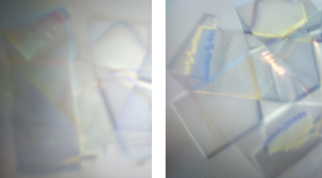
Testing your Viking Compass: What you do. Now take your sellotape and make a criss-cross pattern of the tape. Now look at it in front of a computer screen – put a blank white screen up – through one or both lenses of a pair of 3D (RealD) cinema glasses. You should see pattern of pretty coloured shapes, a bit like a Mondrian painting.
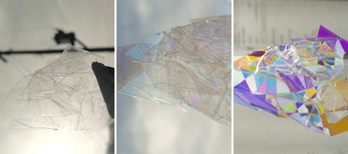
left shows the sky near the sun, middle the sky at 90 degrees, right a screen
Now take the 3D specs and the Sellotape Mondrian outside. Look near to the sun (or 180 degrees away) and it will look colourless. Now turn around until you are roughly 90 degrees to the sun: again the Mondrian turns to pretty colours, although not so pronounced as with the computer screen. That’s it, that’s all you need. Now find a Viking longboat and set sail for New York !
*footnote: I’ve skated over the fact that 3D specs actually deploy circular polarisation, not linear polarisation: but actually you get the same results with linear polarisation.
How good does your Viking compass have to be ? Well, not very, actually. The graph, generated by random numbers from a spreadsheet, shows the random ‘walk’ across the sea with steering which is hugely inaccurate. The graph shows the result of 50 steps taken in random directions +/- 45 degrees of along the Y-axis. Despite the random wanderings, overall this leads to surprisingly good navigation !

Stress and Strain you can see
Stress and Strain can be made visible, which gives a real feel for how objects behave when forces are applied to them. Although computer models are used more often today, being able to see how forces affect things is still a valuable way to help understand and design things.
When things are put under stress (that’s force over area), they stretch (that’s the strain part). The strain is proportional to the stress in many cases (that Hooke’s Law). And when when the things under stress are made of clear plastic, they cause a change in the polarisation of light being transmitted through the plastic. Those changes in polarisation can of course be seen with the aid of polarised light – like a computer screen set to white – and a polarising filter.
Get hold of a suitable s trip of clear plastic, say 3 or 4mm, maybe 6mm thick, 20 or 40mm wide, and 150 to 300mm long. Put a notch in to the edge of the plastic with a file, maybe start with a 3mm deep notch, 10mm long. Set up blank white screen on a computer. Now don some 3D cinema specs or fishing glasses, take the strip of the perspex and bend it. You can just do it by hand for a small strip, or apply larger force using a G-cramp or bench vice. You get see a rainbow of coloured lines over the surface of the plastic, as the pic below. The biggest stress and hence distortions – strain – in the plastic, are where the rainbow lines are closest together – near the notch of course. The large areas with wide lines are where stress and strain is low.

…
…
Simplest Optical Interference
With this you can prove that light is a wave, using just a little laser, a lens, a piece of picture glass, and piece of white card.
What you need
- Laser (an eye-safe type, less than milliwatt)
- short focal length magnifying lens, eg. x10 or x20 lens
- sheet of white card
- sheet of thin glass, eg. the cover on a smallish picture – no need to take the glass off the picture. You will also get interference on window glass, but it is slightly less easy to see on thicker glass.
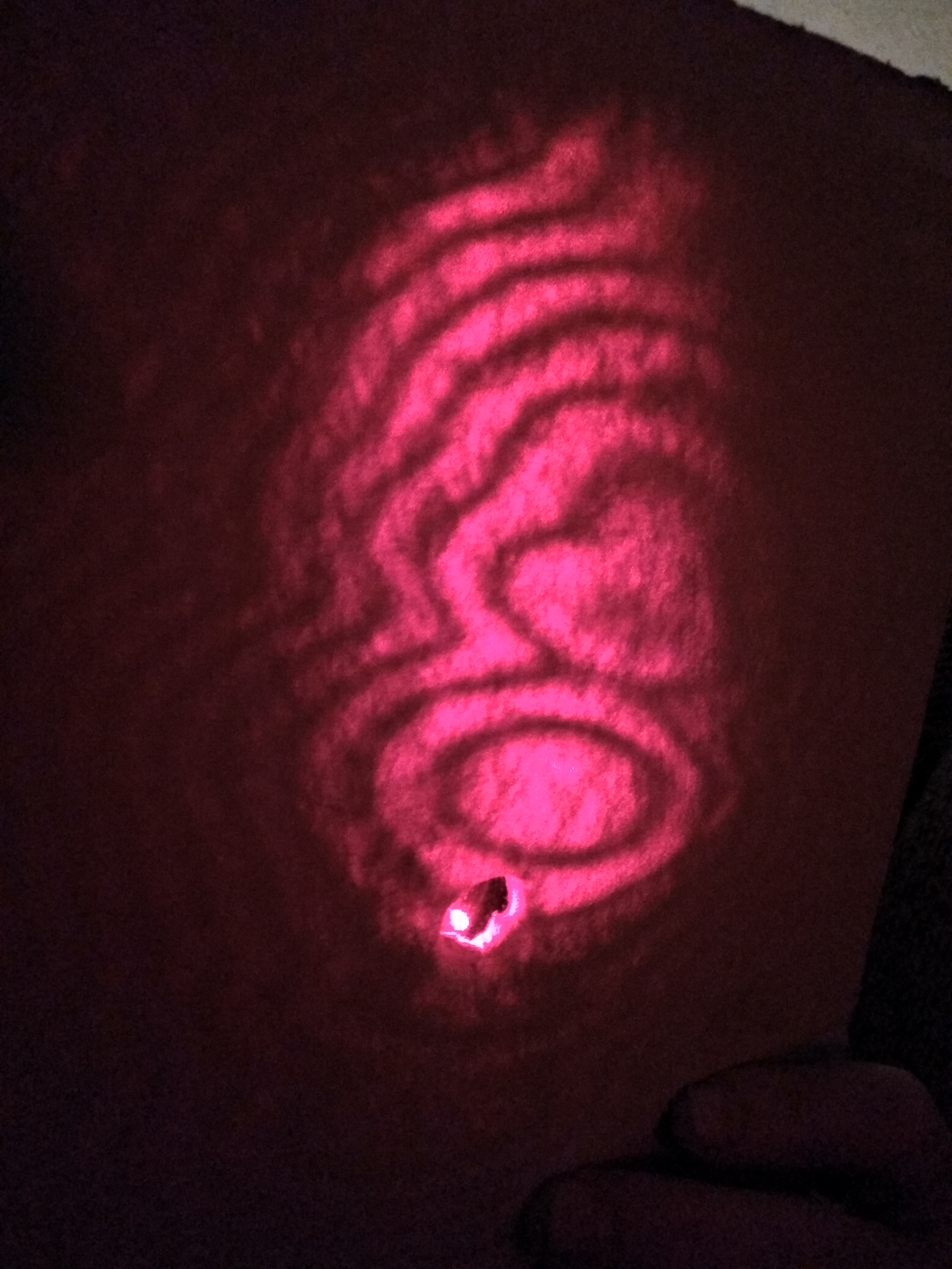
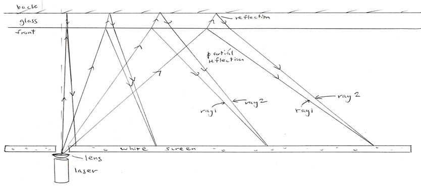
First make a hole in the white card. Now mount the lens over the laser with tape or glue, as you prefer. Remember not to look directly at the laser beam: laser light is very hazardous to the human eye, even the low power eye safe type. (Although in this case the lens means that the laser beam is diverging to a low power per unit area after just a few centimetres). Now shine the laser/lens assembly through the hole in the card at the picture glass and look at the pattern of laser light on the white paper. You should get a picture like that below.
The pattern arises because of interference of light wavefronts reflected from the front and from the back surface of the glass, as in the diagram. This can’t happen, of course, unless light is a wave phenomenon. Light waves can’t line up to reinforce each other or to cancel each other out unless there really are waves. So this simple set-up demonstrates that light travels as waves. * The path lengths of the reflected and double-reflected rays differ as you go off the optical axis, leading to positive and negative interference and hence light and dark fringes as you go from the axis to further out. You might expect to see circular fringes whose spacing decreases as you further from the axis. However, slight variations in glass thickness mean that you tend to see thick fringes near axis and narrower fringes far away, but they are only very roughly circular.
*(Of course, the ‘physics magic’ of quantum mechanics means that light also behaves like particles. The Photoelectric Effect, the analysis of which is what got Einstein his Nobel prize, proves that light is particles. You can show the Photoelectric Effect simply too. It can be done with a charged zinc plate at the top of an electroscope. When you shine a UV light on it, the UV photons, the particles of light, eject electrons, and discharge the plate. )
…
…
The Wet Solar Cell
Doublethink means the power of holding two contradictory beliefs in one’s mind simultaneously, and accepting both of them. George Orwell, 1984
When light strikes certain objects, electricity flows. The photoelectric effect in vacuum, when it was discovered, required the high tech of the day. And today, photovoltaic solar panels need sophisticated semiconductor technology. But you can demonstrate quantum physics and the future of power generation on planet Earth using only a multimeter and a few things you might find in your kitchen. The solar cell in this project must be the world’s simplest. The Ancient Greeks could have constructed one. Archimedes could have tried this technology in his bath before leaping out yelling EUREKA !
Take two lumps of almost anything that are at least slight conductors, dunk them in a salty water, and apply light to one of the lumps, and in many cases, a little electricity is likely to come out. Really ? Really. It’s that simple. But why does it happen ? (And it’s maybe also worth asking: what’s so hard about making a real solar cell ? )
Solar cells allow the generation of electricity directly from sunshine, a key technology for the energy industry of the future. Even if it had no economic significance, however, the photoelectric effect would still be studied intensively. Modern physicists have to employ a kind of “doublethink” to understand the photoelectric effect. The photoelectric effect and, ultimately, the whole of quantum mechanics require that photons must be both particle and wave simultaneously. If light is not composed of waves, then how can we explain optical interference ? But if light is made of waves, then how can we account for the photoelectric effect ? Albert Einstein’s 1905 theory about the photoelectric effect, combined with Max Planck’s earlier work on black body radiation, laid the basis for what we now call quantum mechanics, one of the foundation stones of modern physics. John Stachel tells some of the story in Einstein’s Miraculous Year. Incidentally Einstein was presented with the Nobel Prize for Physics for this work on the photoelectric effect, not relativity and gravity.
Early-nineteenth-century scientists like Edmond Becquerel in France, playing with platinum electrodes in different solutions and later with silver iodide–coated silver electrodes in acidified water, were probably the first to stumble on the phenomenon of photoelectrochemistry. Mary Archer tells how young Becquerel’s discovery was greeted with disbelief by other scientists in his day, the situation exacerbated by the problem that no one had an explanation for the results, quantum mechanics being very much in the future in 1839.
Liquid solar cells–such as those using ferrous salts and iodine, thallous sulfide, or selenium, and the copper/copper(I) oxide system system we used here—had been discovered by the early 1900s; the first recorded scientific paper on electricity from copper in sunshine was published in Physikalische Zeitschrift in 1904. Solid-state solar cells have been around since the early days of the space race. There are now fields full of thousands of square meters of them generating electric power for all of us, and they are common in consumer items like calculators. Despite this, nobody has ever marketed “wet” solar cells. Quite why this should be seems a bit of a mystery, since they are so simple to make. Perhaps the answer lies in mundane but important issues like corrosion, sensor lifetime, leak-proofing, and so forth.
What You Need
- Clear container eg. wine glass or tumbler size
- opaque, ideally black, nonconductive material: black plastic or paper will do
- salt (sodium chloride, NaCl) or bicarbonate of soda (sodium hydrogen carbonate, NaHCO3) or alternative soluble metal salt
- two electrodes of : thick bare copper wire (oxidized); Fool’s Gold; silicon (pieces of broken solar cell or electronic chip); & other things to try
- multimeter with sensitive hundred microamp or so scale
- Multimeter (current meter 0–100 or 0–200 microamp or so)
- Reading lamp – or sunshine !

What You Do: Hold two pieces of copper wire in pliers so you don’t burn your fingers, and heat the wires simultaneously in a flame until they glow red; continue heating them for a few seconds longer, and then remove them from the flame.
Dissolve a teaspoon of bicarbonate, say 5g, (sodium bicarbonate works best, but ordinary table salt works well too) in a cupful of warm water, and then put the solution in the clear container. Now dangle the wires in the container. Position one so that the piece of black cloth will largely prevent light falling on it, perhaps forming the black cloth into a tube to partially enclose the electrode. Connect up the multimeter. Its that simple!
In the dark, the cell should give an output of less than 10 microamp, but with a strong light (sunshine or a reading lamp at point-blank range, for example), you will get at least 30 microamp and maybe as much as 100 microamp of electric current. Although this is not a lot of power, it’s plenty to operate an electronic circuit like the one I’m going to suggest in a moment. With larger electrodes you will get much more current.

How It Works: What’s going on here? A photon—a quantum, or “particle,” of light—collides with the electrode surface and is absorbed; the photon’s energy pushes a negatively charged electron out of its normal orbit around a positively charged nucleus in the electrode. As a result of this, the electrode acquires a small negative charge. The charge produces an electric field which can push the electrons created by the light from the illuminated to the dark electrode via the electrode wires, and then the current passes through the conducting solution with its charged bicarbonate (HCO3– ) and sodium (Na+ ) ions, forming a complete circuit and allowing current to flow continuously. A more intense beam of light contains more photons than a less intense beam and will eject more electrons and produce a larger current.
This is not an obscure phenomenon, destined only for dusty academic bookshelves. Solar cells are a hot research topic. Sunlight offers a great abundance of power that just requires conversion into useful form. Recently, some important forward steps have been taken in research on liquid solar cells. Photoelectrochemical solar cells just might one day rival their silicon cousins. Researcher Michael Graetzel has made cells using titanium dioxide electrodes stained with organic dyes that generate power almost as efficiently as silicon solar cells and that could be much cheaper to manufacture.
The Wet Photoelectric Alarm: This phenomenon can actually be useful: for example, in a photoelectric alarm. The current from the cell will be too small in general to do something directly, like operate a motor, even the smallest motors. However, a device that uses our wet solar cell as a sensor is quite straightforward and will work with a small glass cell.
Although the circuit I’ve drawn could be made more sensitive, it is intended to trigger at 10 microamp or so, to avoid false triggering due to stray currents that flow even in the dark. The circuit triggers when it receives light. If you wanted to make a “break-the-beam” burglar alarm, you could change the circuit so that the beeper turned off at 10 microamp input current and switched on when the current fell below this. An alternative might be to use the sensitive inputs of a small microcomputer like the BBC Microbit to make the wet solar cell output useful, with the additional advantage of being able to program the computer to perform more complex actions.
The Science and the Math; Light is electromagnetic waves. To explain the photoelectric effect, Max Planck and Albert Einstein figured out that light must come in little packets, or ‘quanta’. The light quanta – photons – each have an energy given simply by Planck’s constant, h, and their vibration frequency, f:
E = hf.
For example, blue light, f = 6.2×10^14, has a quantum energy of 4.1×10^–19, or 2.6 eV; and red light, f = 4.3×10^14, has a quantum energy of 2.8×10^–19, or 1.8 eV.
What convinced Einstein that light must come in quanta? Many experiments showed that a less intense beam of light contained fewer photons, ejected fewer electrons, and thus produced a smaller current than a more intense beam; whereas a beam of light with less energy in each photon (red light, rather than blue light) would often, depending on the electrode material, produce no current at all. Experiments showed that there was a minimum energy needed to propel the electron out of electrodes such as copper oxide. If the quantum of light had too low a frequency, no electron would be emitted and no current would be measured, no matter how intense the beam of light. It was this particular feature that led Einstein to his theory of photoelectricity and, ultimately, to quantum mechanics.
What does all this have to do with our wet solar cell, you ask? Well, the key to our cell is the bicarbonate solution, which essentially acts as a wet contact to the CuO layer on the electrode. The brown copper(I) oxide is the photosensitive element that emits electrons when it receives photons.
You could modify our cell by using a different electrode for the dark electrode, which, after all, is there simply to collect the current. However, using two identical electrodes works well because the cell generates no current when both electrodes are in the dark. With two different electrodes, the system tends to behave as a regular chemical battery and produce current even in the absence of light. This may explain why the effect of light on the electrodes and chemical solutions of a battery was not noticed by the pioneers of electricity, even the great Michael Faraday. Given how simply the effect can be demonstrated, its absence from this early work is curious.
How does all this apply to our alarm circuit? The circuit simply amplifies the current from the electrodes and feeds it to the beeper circuit. An idealized operational amplifier (op amp) can be considered to be a black box that tries to zero the current into its inputs and keep their voltages the same by pushing current out of its output. In our circuit, the current in the input leads from the cell is drained away by the 330-kohm resistor, such that the idealized op amp has zero current in and the same voltage at each input terminal. To achieve this, the op amp pushes moves its output voltage until the negative input terminal is once again at the same potential as the positive input, with zero current flowing into either terminal. Suppose the photoelectric cell were giving 3.3 microamp short circuit current. When the op amp output gives 1 V on the output (plenty to operate the beeper via the transistor), it will push 3.3 microamp down the 330-kohm resistor, current exactly equal to the photoelectric current, assuming that the input terminals can be considered to be near ground potential. In effect, this circuit converts an input current, Iin, into a voltage, Vout, as described by the following equation:
Vout = Iin R
where R is resistance (100-kohm, in this case). So
Vout = 100,000 x Iin.
You might be mistakenly thinking that this is Ohm’s law and that you could achieve exactly what this circuit does with just a resistor! If so, you are missing the fact that the output voltage of the op amp here is provided with a considerable current capability, 20 microamp or so, whereas a 100-kohm resistor on its own could provide only a microamp before the equation would cease to apply. The transistor boosts the op amp current to the 200mA or so that the beeper needs (although some piezoelectric beepers take rather less current than this). The capacitor across the beeper helps to stop the beeper from interfering with the circuit that switches it on—in this case, our photoelectric cell.
And Finally . . . Other Electrodes
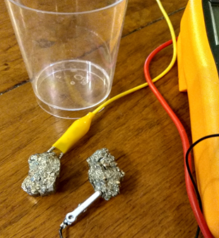
Now try some other electrodes. You’ve sailed all the way to Godforsakenville, Nowhere Island, dug a mine, and found Fool’s Gold ! Fool’s Gold (iron sulfide) is almost completely worthless: You feel very Foolish. But wait ! There IS something Fool’s Gold is good for: wet solar cells. Crystals of fool’s gold, iron pyrite, are conductive, and, even more important, they emit electrons when illuminated. Try to find two elongated lumps of pyrite. Check for electrical conduction, and then clamp alligator clips to the lumps and immerse them in a sodium bicarbonate or salt solution, as you did with the copper wire. The photoelectric effect will probably be weaker than for the copper, so try hiding the cell underneath a blanket with a reading lamp inside and switching the reading lamp on and off. A few microamps of photocurrent should be possible with lumps of pyrites a few centimeters long.
Another thing that’s good to try is silicon. You can get this most easily from some piece of electronics, and within electronics, most easily from – guess what ! – a (silicon) solar cell ! You don’t need the solar cell to be intact. Just two broken pieces will serve.
Naturally enough, pieces of solar cell silicon will function well as wet solar photosensitive electrodes—although perhaps not as well as they do in a solar cell. A solar cell has a structure in which the electrodes gather electrons and “holes” (these are missing electrons in the band of bound electrons; in a semiconductor these holes behave like positive charge carriers) generated by incoming light. Dunking pieces of solar cell in a conducting solution shorts out this structure and reduces the output you can get. Two 5-mm squares of silicon cracked from a solar cell should give 20–30 mA under a reading lamp.
Silver compounds are used in photography because of their sensitive reaction to light, and therefore silver-based electrodes might be expected to give photoelectrochemical effects. If you can find some unwanted silver, some broken jewelry perhaps, try silver electrodes in salt solution. If you can get one of the systems working well, can you make a usable solar battery out of it ? How many volts can you get ? Could you power something like, say, a quartz watch with it ?
References: Archer, Mary D. “Origins of Photoelectrochemistry.” Fifth BOC Priestley Conference, Birmingham, U.K., 1989, pub by Roy Soc Chem, 1990
Einstein, Albert. “On a Heuristic Point of View concerning the Production and Transformation of Light.” In Einstein’s Miraculous Year, ed. & with introduction by John Stachel with Alice Calaprice, Sam Elworth, and Trevor Lipscombe; Princeton University Press, 1998). Original in German in Annalen der Physik, Vol.17 (1905) Pp.132-148
Graetzel, Michael and A. Hagfeldt “Light induced redox reactions in nanocrystalline systems” Chem.Rev., 95, 49-68 (1995)
Hallwachs, W. Physikalische Zeitschrift 5 (1904): 489–499.
Sorry, more coming soon…
…
…
Exponential Decay of Glow-in-the-Dark
Here we take a scientific look at glow-in-the-dark chemicals, which emit light based on energy from chemical reactions (‘Lightsticks’) and glow-in-the-dark phosphorescent paints and inks, which rely on energy absorbed during ‘charging’ by light. It was the study of phosphorescence which led to the discovery of radioactivity in the late 19th century.

What you need:
- Lightsticks and/or phosphorescent paint / sticker/object
- standard transistor such as BC540
- photodiode, ‘large area’ type preferred (they are just 3mm or so square)
- 10k resistor to limit current
- choc-bloc screw terminal to connect parts
- multimeter, USB multimeter to log data directly onto a PC (or Microbit – see below)
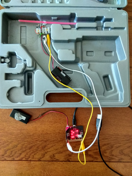
- plastic (Polypropylene type) box, with flex-hinge moulded in, as supplied with tools such as soldering guns, drills etc.
What you do: The lightstick or phosphor is mounted just a millimeter or two from the photodiode inside the light-tight box. Wires are led out to the multimeter outside the box. The photodiode should be near to the hinge and face towards the hinge: this should minimize light leaks.
The Circuit: The circuit uses a photodiode to convert light into current, and a single transistor to amplify this tiny current to a few or tens of microamps. The photodiode used is basically a tiny solar cell, a silicon PN junction where roughly speaking each incoming photon that is not absorbed in some other way releases an electron. Other photons of course are wasted, for example, just heating up the silicon).
Phosphorescence produce a glow which is typically 100x or so brighter than glowsticks, so we need to use a higher gain to amplify the current in the case of phosphorescence measurements. Probably the easiest option is to use a Darlington pair instead of the single transistor, as suggested in the circuit diagram. You can use choc-bloc terminal strip to hook up the parts (or solder onto a prototyping stripboard (‘Veroboard’) if you prefer).
Once you have everything hooked up, the next thing to do is check for dark current and for light leaks. Put the multimeter on a 200 or so milliAmp scale. Close the lid on the box, ensuring that the wires lie flat between the box halves, and leave on the opposite side to the photodiode. Adjust the multimeter to read out a suitable microAmp (uA) scale. You should find 0 ! However, there may be a slightly leak through the box material. I found that black and silver boxes were slightly less transparent than other colours. There may also be a bad joint on the box, although most I tried were surprisingly good. If there is a current, check that it really is down to a light leak by blanketing the box with a dark towel or cloth. You can try positioning this leaving light entering from the room, or from a torch, until you find that leak. You can use black tape to seal leaks. Once you have sealed up the leaks, you should find that the current is very low indeed. However, particularly with a super-sensitive
Now break a lightstick, or charge up a phosphor in sunlight, and then install it next to the photodiode. Now close the box lid again and start taking readings.
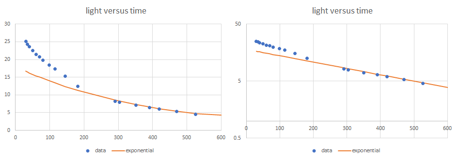
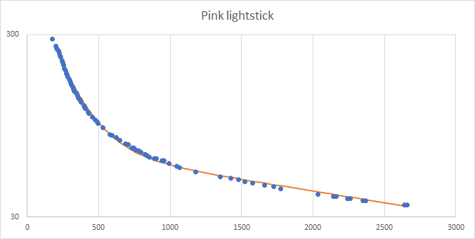
Data on exponential decay: once you have some data, plot, and you may well get something like that above. The data above is from a yellow lightstick. In this run, using a single transistor amplifier, the initial photocurrent fell rapidly, and has one time constant, while later data has a different time constant. An exponential in the example above seems fit nicely to the latter part of the test. You can also fit an exponential to the early part of the test. And in fact a model with two exponentials added up fits pretty well. This suggests that two chemical reactions, one slow, and one fast, both produce light.
There may be anomalies caused by heating of the lightstick: there is a chemical reaction taking place which releases heat as well as light, which will tend to increase the light emission but reduce the time constant. Also, when you bend it to and fro to crack the peroxide container and mix the chemicals, you may well also add heat from your hands.
The cooling of hot object tends to follow an exponential fall from its initial temperature to the ambient temperature. The effect is sometimes called Newton’s Law of Cooling. It follows simply from calculus, by integrating the equation for heat flow: this, of course, might lead to confusion with the exponential decay of the light output anyway.
Glow-in-the-dark: Easier Data Collection with a Microbit
You may already have gotten a bit bored taking the data over many hours to get the longer time sequences of data from glow-in-the-dark effect. Why not hand over the data-taking to a friendly helpful computer like the credit-card-sized Microbit. You can program the Microbit to process the data, choose how which data points to read, and then log them onto a
PC laptop or desktop computer via a USB lead. The Microbit is introduced in much more detail in the page on Microbit projects on this website.
You could just take readings with a multimeter which will connect to a laptop computer via a USB lead. However, this will result in a large volume of data which is pretty useless. The particular advantage of the Microbit over a USB multimeter is that it can be programmed to readout with a frequency decreasing over time, matching the slowing of the decline in photocurrent. Alternatively, the Microbit can be programmed to record a new reading only when a new reading is different from a previous one by a least some minimum value, avoiding taking many readings which are the same.
A slight change in the circuit is needed to get the output in mV, rather than in uA, for the Microbit. Try a 100k or so resistor from transistor collector to +3V, with in parallel a 4.7uF capacitor, as suggested in the circuit below. (Many other values of component will work well, by the way).
The resistor converts current to voltage, of course. The effect of the capacitor is a bit more subtle. The Microbit draws a certain amount of current when it takes a reading with its analog-to-digital converter (ADC), and this can cause it to read inaccurately. The capacitor stores a charge and so stops the reading changing while the Microbit is taking it.
Here is the kind of program you might like to write for the Microbit, in this case taking a reading every time it has changed by at least 6mV:

The Microbit sends data via serial write along the USB lead. A simple way to record the data that comes over the USB is to use a ‘terminal emulator’ on the PC, such as TeraTerm. Data, once logged, can be moved, often by drag and drop, over to a spreadsheet, eg. on Excel, and analyzed fully. Below is a plot taken by a system with the program above. (Note the long times involved – but the computer is very patient !).
The double exponential fitted to the curve is:
I = Ii exp(-t / Ti) + Ij exp(-t/Tj)
where Ti and Tj are the time constants ( times half-life) and Ii and Ij are the starting photocurrents for each exponential. In this case, we have Ti = 180, Tj = 3400, Ii = 550, Ij = 75.
Sorry, more coming soon !
…
…
The Viking Compass
It is now known that long before history began on the American continent, Viking sailors braved the Atlantic fog and storms and the problems of food, water and scurvy in the long sea crossing, and landed on the north-east coast. They had no satellite navigation, no GPS or Transit, no hyperbolic or other radio beacon navigation, no gyros, not even a humble magnetic compass.
They could, of course, have used the sun on sunny days. But the sun sweeps across the sky, so you need to have some idea of time, otherwise you will steer a strange course. Think if you a trying to go west, then you need to go, on the average, at right angles, to the right of the sun. But in the morning you would be going south, and in the evening north. But applying some sense of time of day, by estimating the elevation of the sun from the horizon or the heat of the sun or otherwise, you can steer fairly well with the sun fully visible. But if the skies are cloudy, it gets much harder.
It is easy to show that you don’t need to steer a particularly straight course to go places, at least if you don’t mind travelling 10% slower than a straight course. You can demonstrate this with a simulation, which you can try on a spreadsheet, or with a BASIC computer program on your PC or laptop.
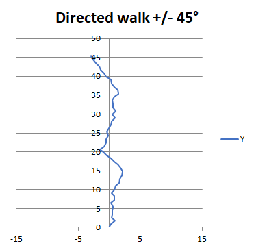
Above you see the result of calculating 50 steps taken in a direction random in an arc of 90, 45 degrees either side of nominal course. Despite the seemingly bad deviations of course, these Vikings, perhaps sailing with the navigational aid of beer, actually get there 90% as quickly as their sober cousins. So you don’t need a particularly good compass to steer a pretty good course, particularly if the place you are heading to is pretty large, like a continent !
What you need
- Sellotape or other similar ‘cellophane’ clear sticky tape
- 3D polarized glasses, a pair (or even half of a pair)
- alternatively, a pair of fisherman’s polarized glasses, or just a piece of ‘polarized’ clear plastic such as Polaroid
- some degree of daylight, with sunshine or not too much cloud
- some idea of the time of day
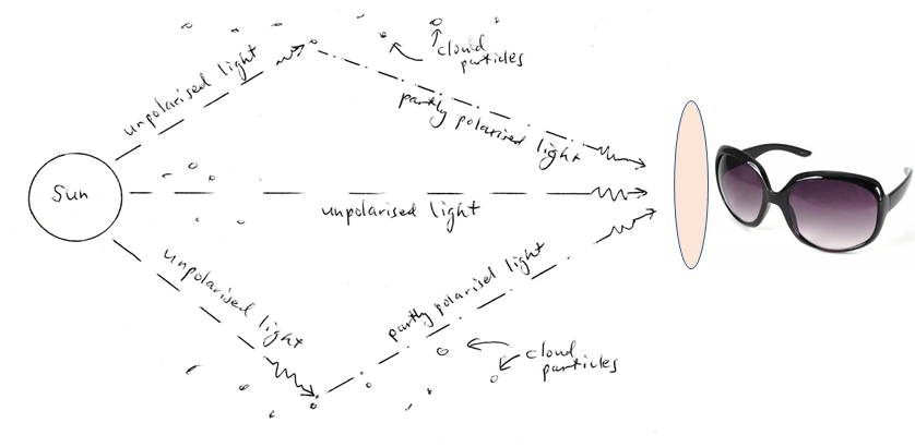
As the diagram shows, light from the sun is unpolarized. However, once it has been scattered from water droplets or ice particles in clouds in the atmostphere, it is partially polarized. This polarization can be revealed with polarized or 3D cinema glasses behind a Mondrian of crossed pieces of Sellotape or similar.
First make a Mondrian. This is simply a random sheet made from a half dozen or dozen pieces of tape all crossing over each other. Test this on a computer screen or TV screen, set to white. These mostly emit 100% polarized light, because they use LCD technology, which relies on polarization. You should see strongly coloured images like those above.
Now take your ‘Mondrian’ and 3D glasses outside, in conditions which have degree of daylight, with sunshine or not too much heavy cloud. Look around the sky with your Mondrian held in front of one or other of the lenses of the 3D glasses (probably easier to close the eye that doesn’t have the Mondrian to start with. You will find pretty quickly that if you look near to the sun, or where the sun would be if it were not obscured by cloud, that you see just colourless tape. Similarly if you look 180 degrees, in the direction opposing the sun. But half way around, at 90 degrees to the sun, the Mondrian acquires colours, as in the picture. That’s the Viking compass effect. It may not seem like much, but it would allow you to deduce on most cloudy days a rough direction for the sun. And as we discussed, rough is enough.
As you can see from the images, the polarization effects in skylight, which is only partially polarized, are much smaller than with the 100% polarized light from a TV or computer screen. You can try to do the same, although it isn’t as easy, with pieces of Iceland Spar, the mineral which the Vikings might have used instead of polarized glass.
more coming soon…
